
It’s been a little while since I have reviewed an onroad car and with the brand spanking new Associated TC6.1 landing in my lap for a review, you could have guess that I am feeling more than ecstatic on getting this rig on the track. As with most serious racers, which includes me, I prefer a new car in kit form versus a RTR vehicle. Along with competing with your new race kit, building and knowing it inside and out is part of the whole RC experience that makes it truly enjoyable. I’m stoked to build the TC6.1 and I’m going to take you along for the ride. Lets get started!
-
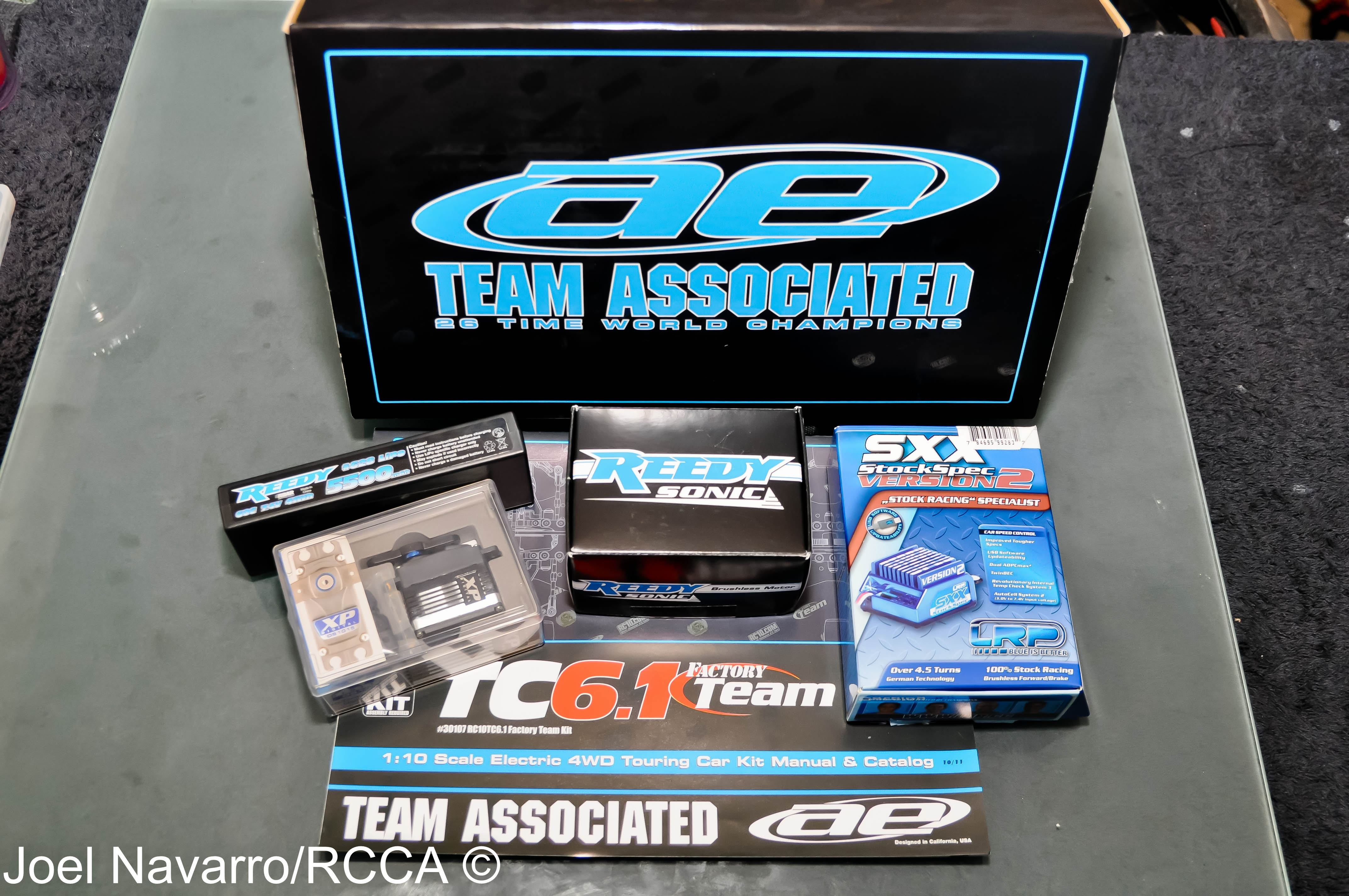
- Associated sent me the TC6.1 sedan along with all the goodies that will be going in it.
-
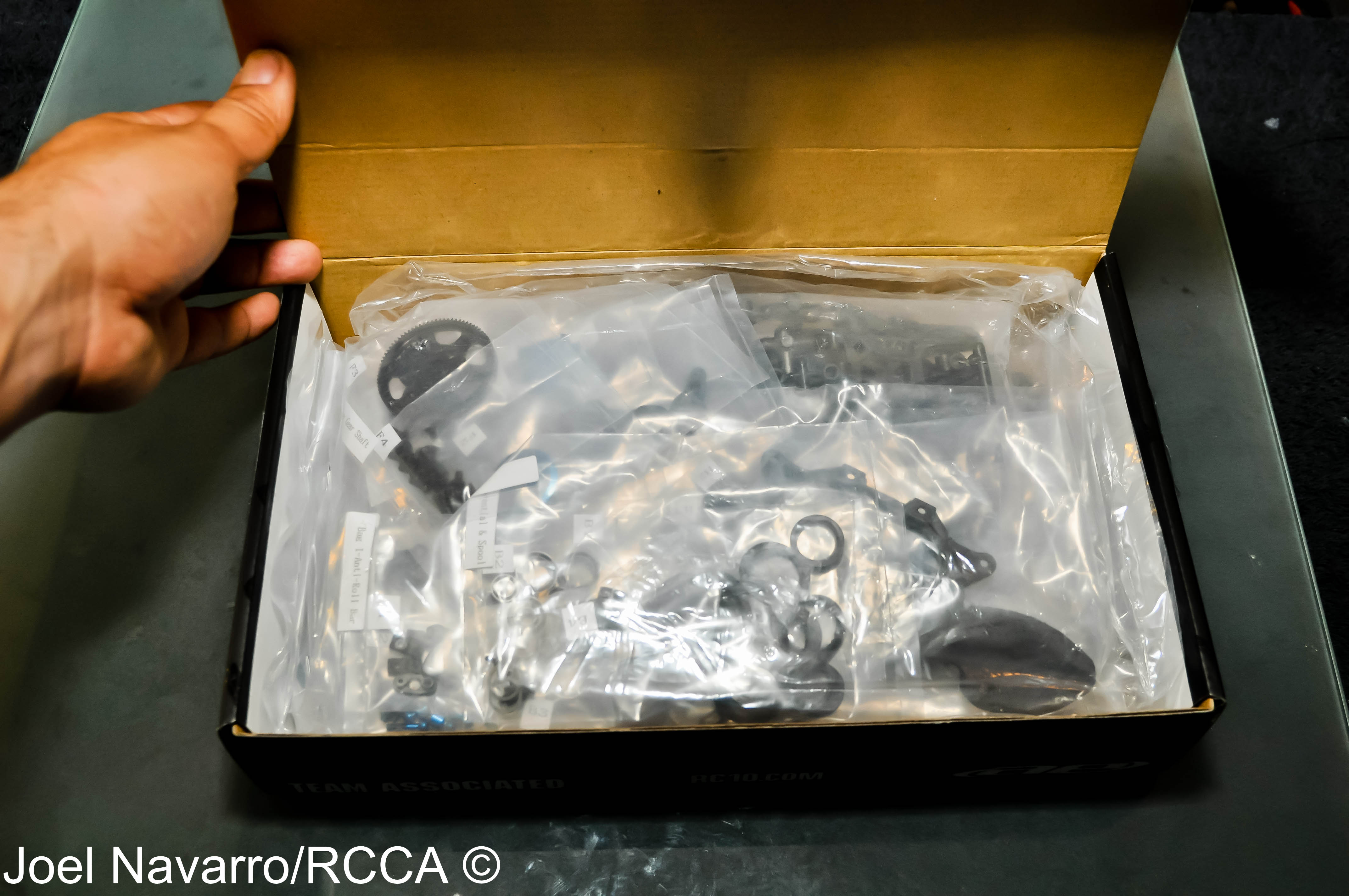
- This is what you see when you open the box. Everything is in numbered bags that correspond to a step in the instruction manual.
-
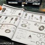
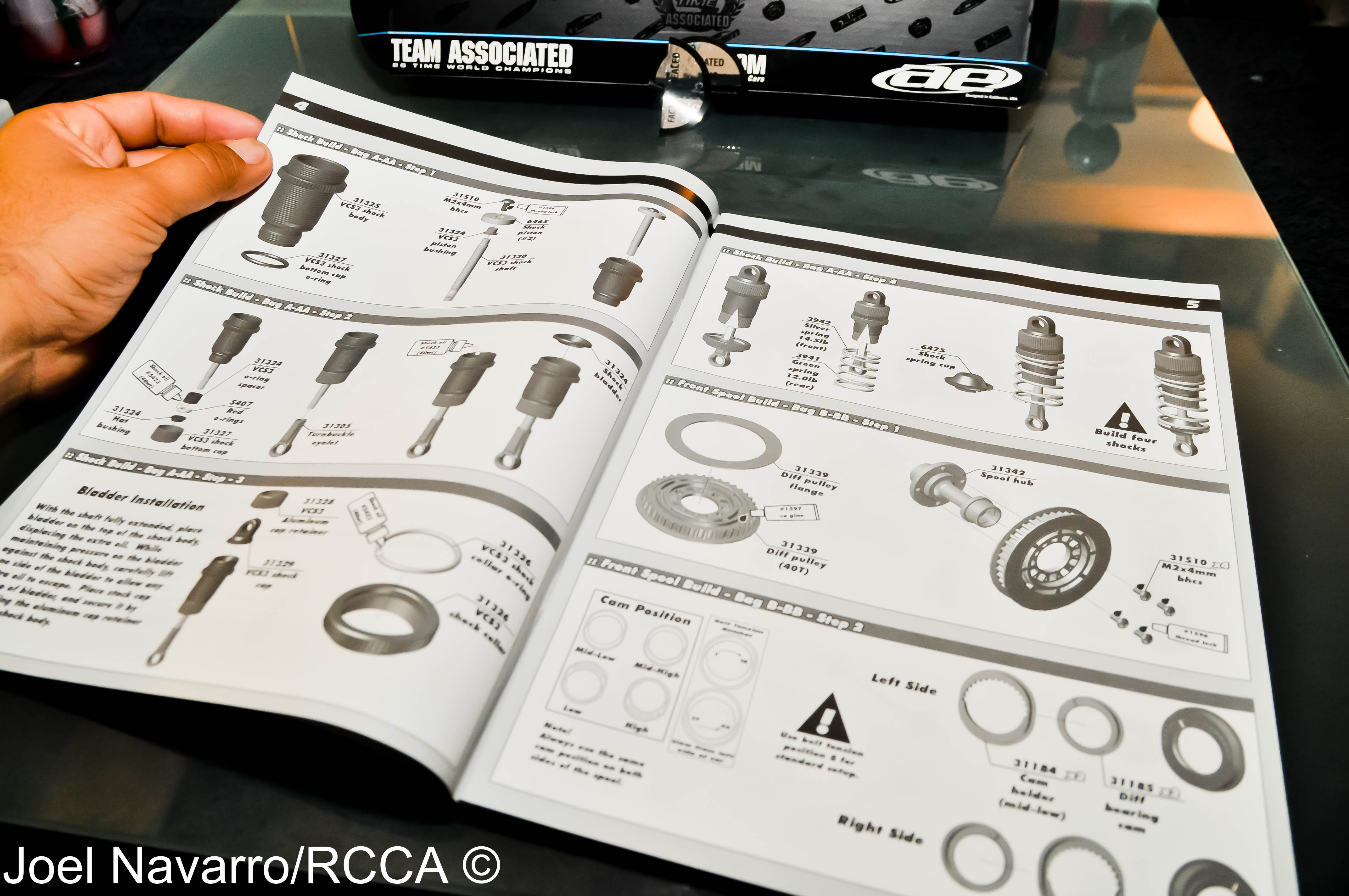
- The instruction manuel is well laid out and easy to follow making this build a breeze.
-
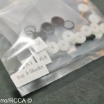
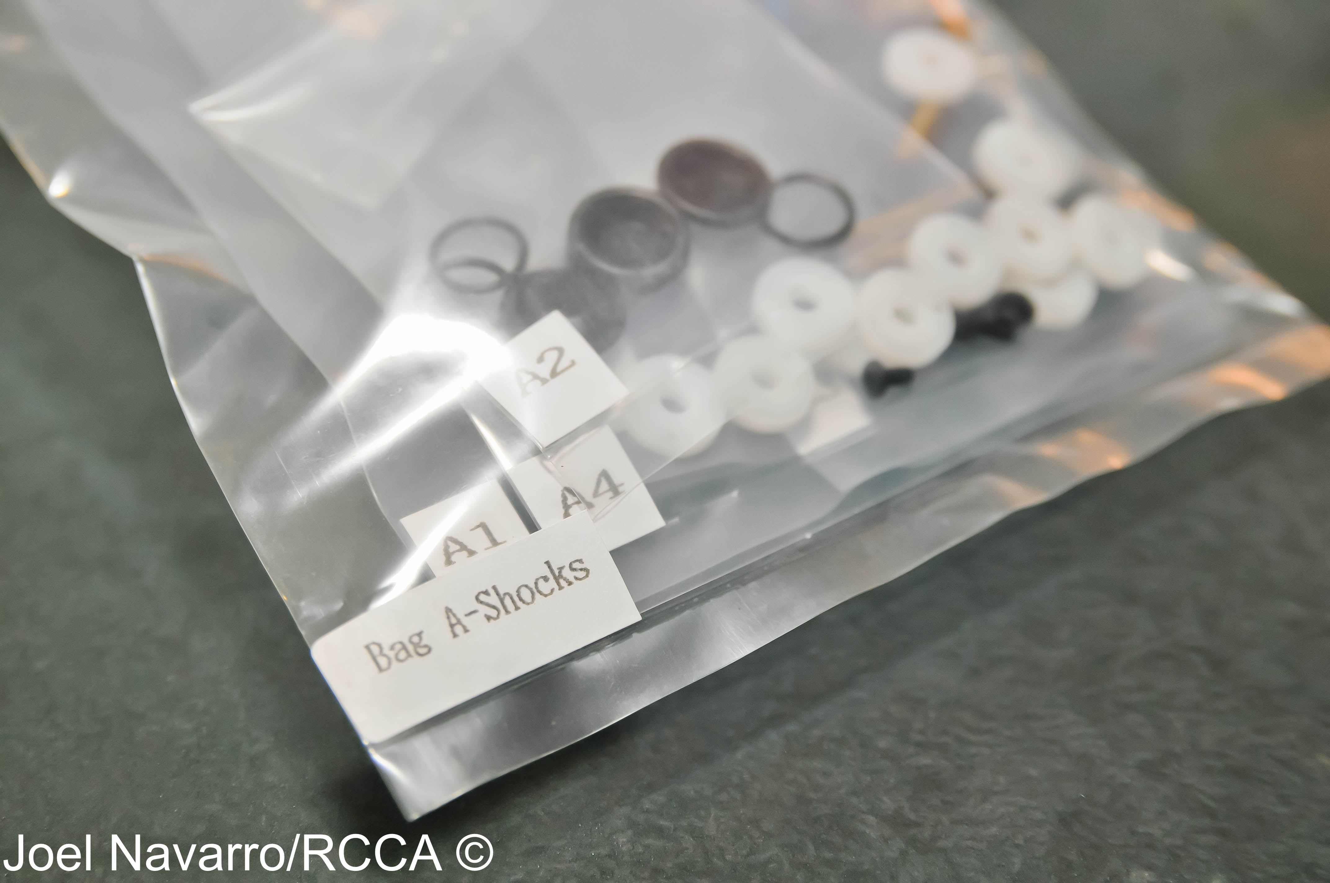
- All the bags are clearly marked and contain all the pieces you will need for a specific assembly step.
-
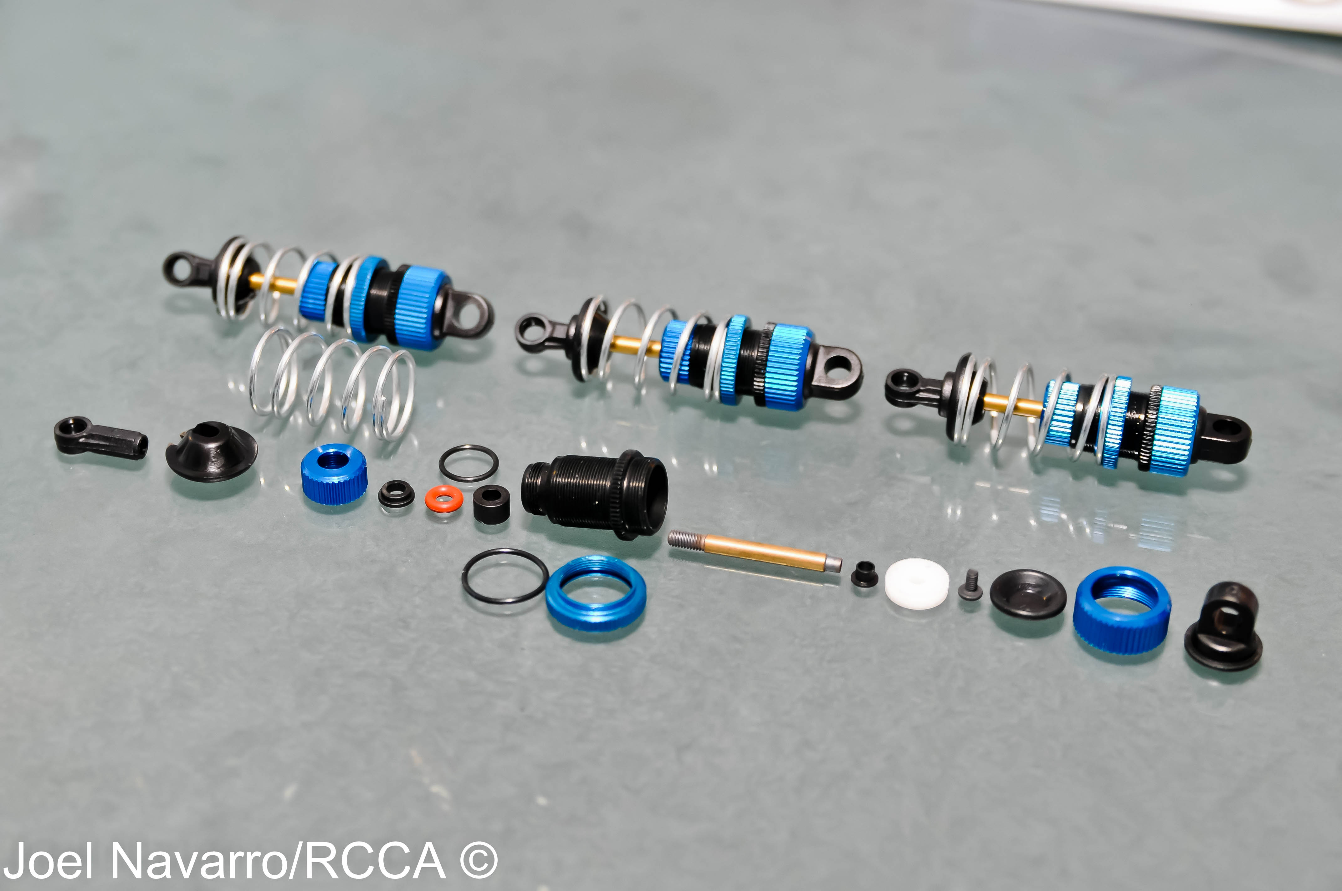
- Most car kits have you assemble the shocks last, AE does it first which is fine by me. Assembling shocks is sometimes messy and I like to get it over with. The TC6.1 shocks went together though with little to no mess at all.
-
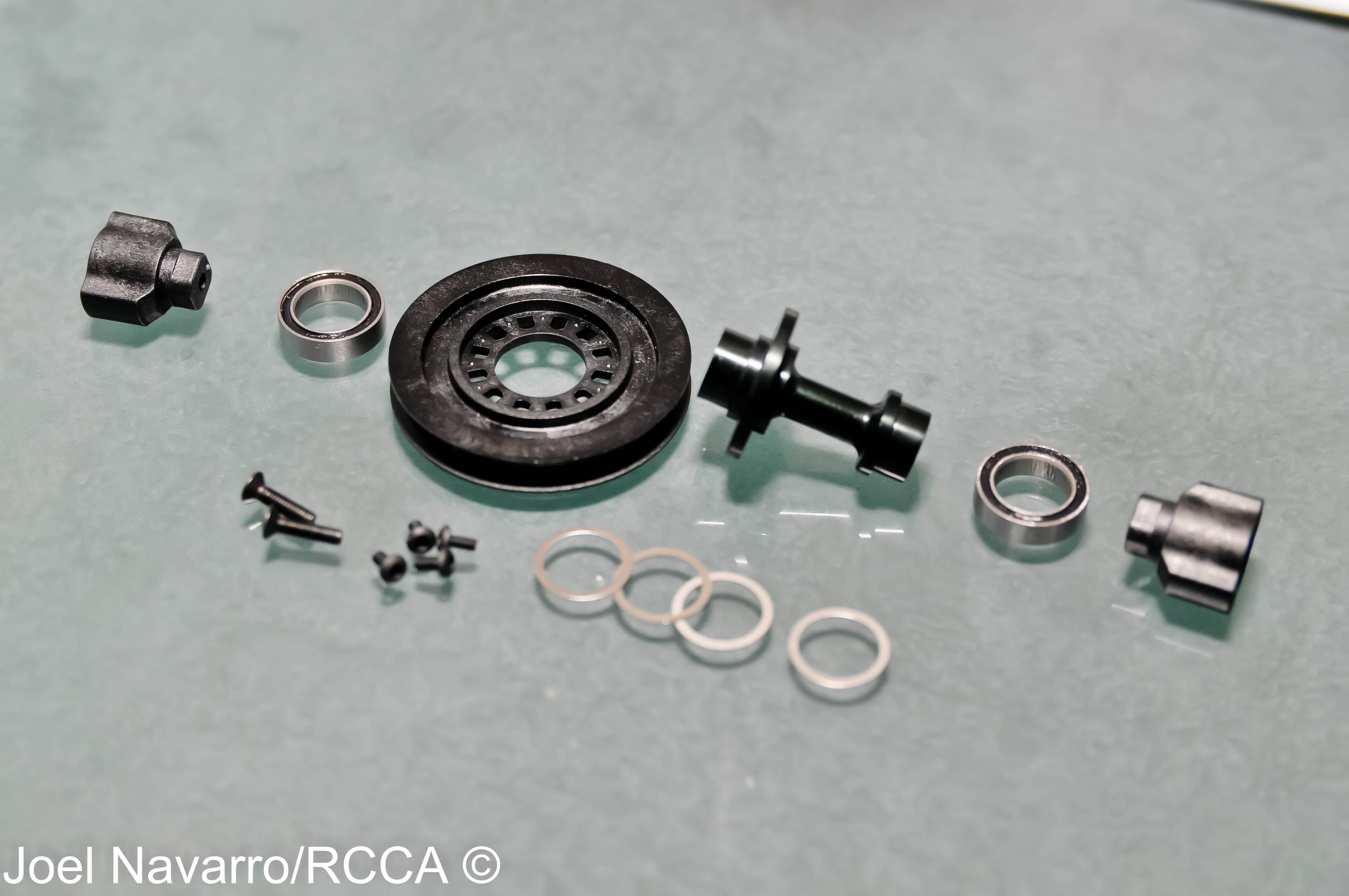
- Next came the front spool. The pulley fit a little snug at first, but I free’ed it up a little with a reamer.
-
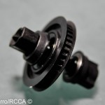
- Here’s the assembled spool. The composite out drives house the dog bones that use plastic blades. I think it will be a while before these babies wear out!

-
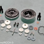
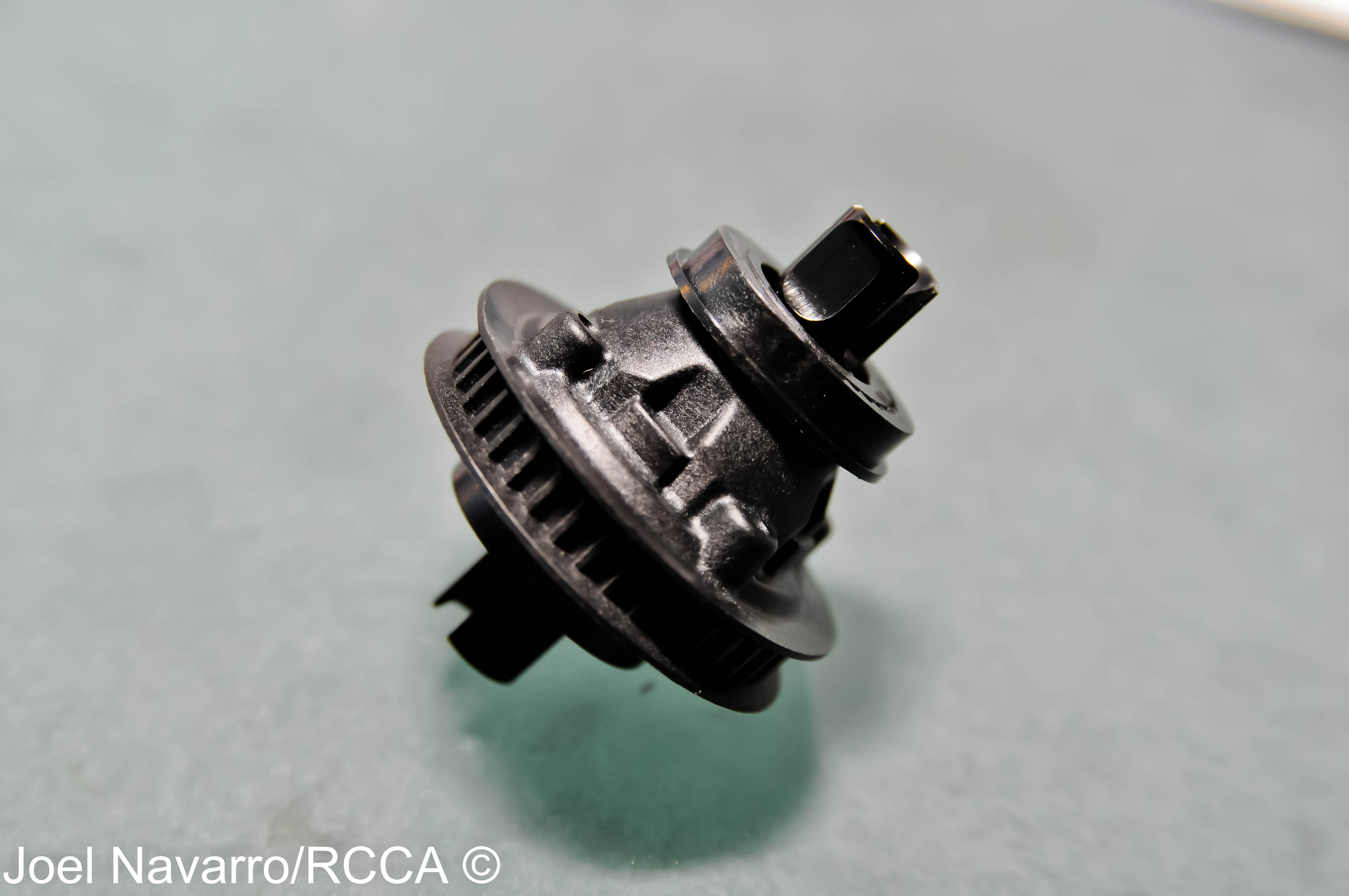
- There’s a recent trend of gear diffs in 1/10th scale vehicles and I’m all for it! It means less maintenance with the same consistent diff action.

-
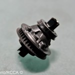
- Here’s the finished rear gear diff. If you have experience assembling gear diffs, this unit will go together the same way. Its finished off with filling it with 40wt shock oil.
-
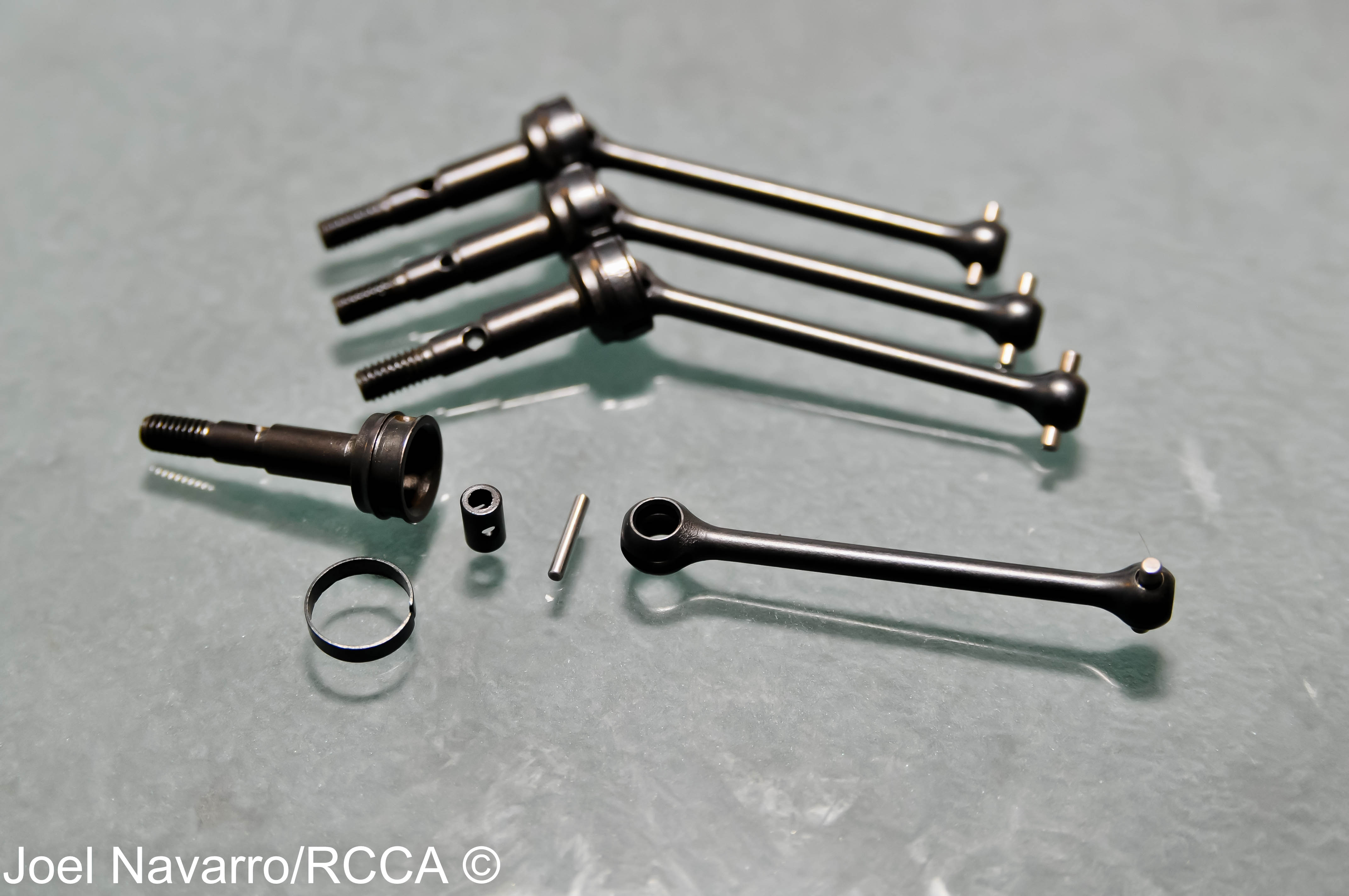
- One thing I’m liking about the TC6.1 is how symmetrical it is. Here is the first example of this. All the universals are the same front and rear so you don’t have to worry which is for which. This also cuts down on spare parts cost.
-
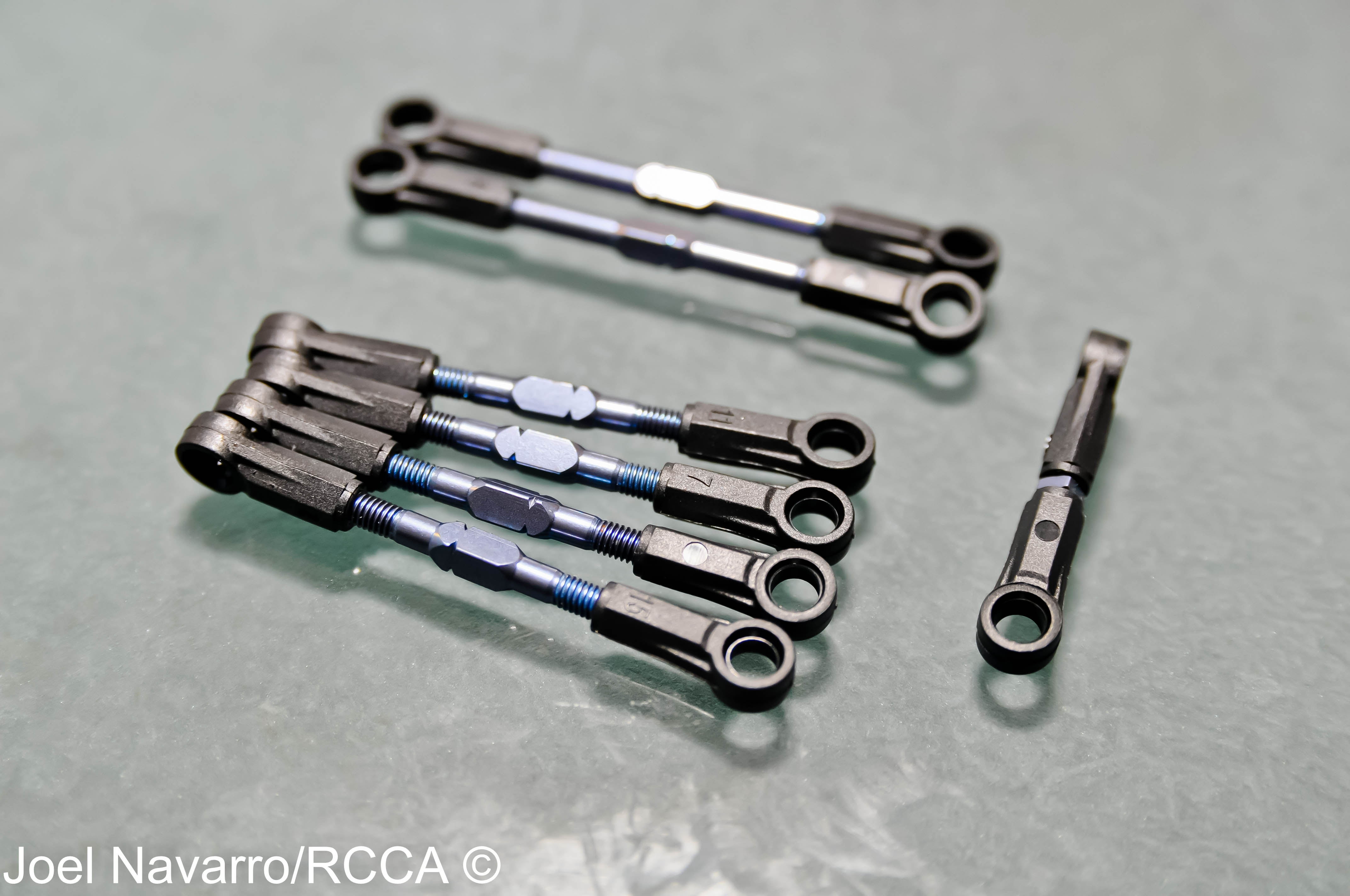
- One of the other steps I don’t look forward to is putting together all the camber/steering/servo links, but the TC6.1 pieces went together like butter. One thing I’m doing more on a regular basis is putting a dab of AE black grease on the turnbuckle so it screws in easier into the plastic ball cup.
-
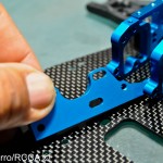
- Next step was to mount the front suspension arms to mount to the blue aluminum bulkheads. There is a ton of adjustability options possible in the TC6.1’s suspension that include track width, caster in the arm, roll center and suspension arm kick up.
-
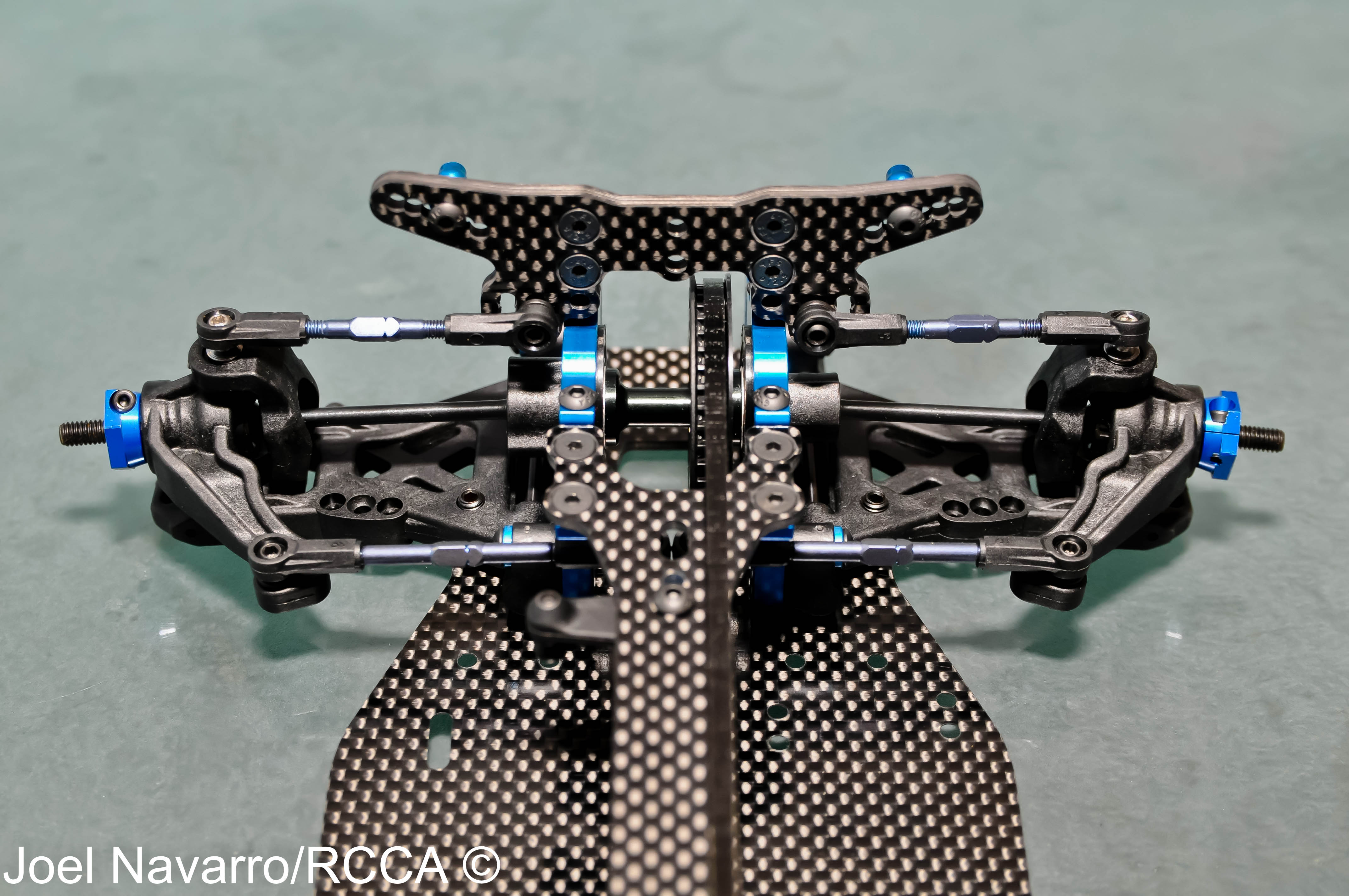
- Mounting the front suspension to the chassis was next. Another example of symmetrical. The bulkheads and suspension arms are the same on the left/right side of the car.
-
- The same steps were repeated for the rear suspension arms.
-
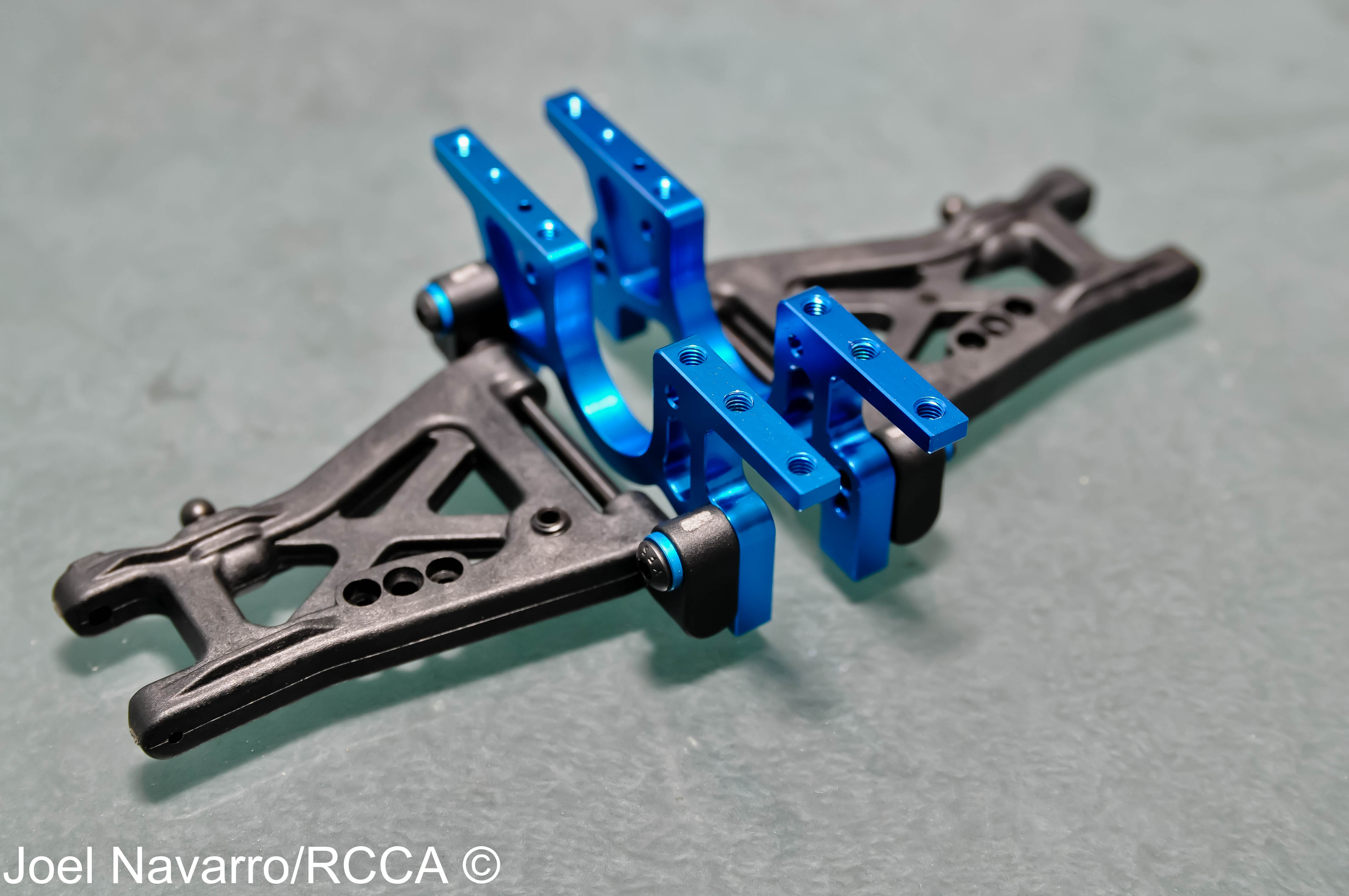
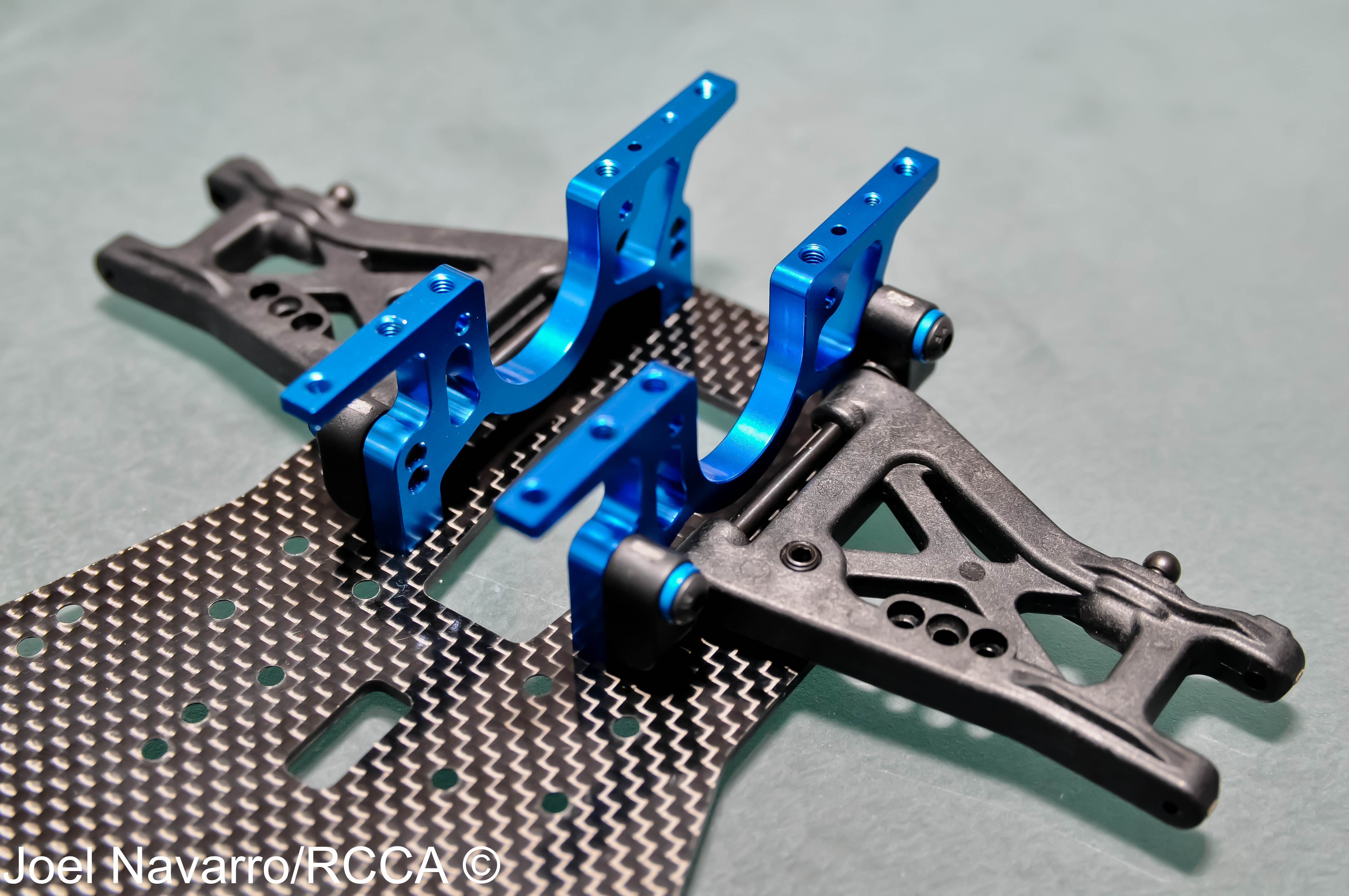
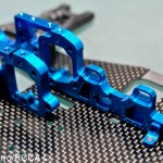
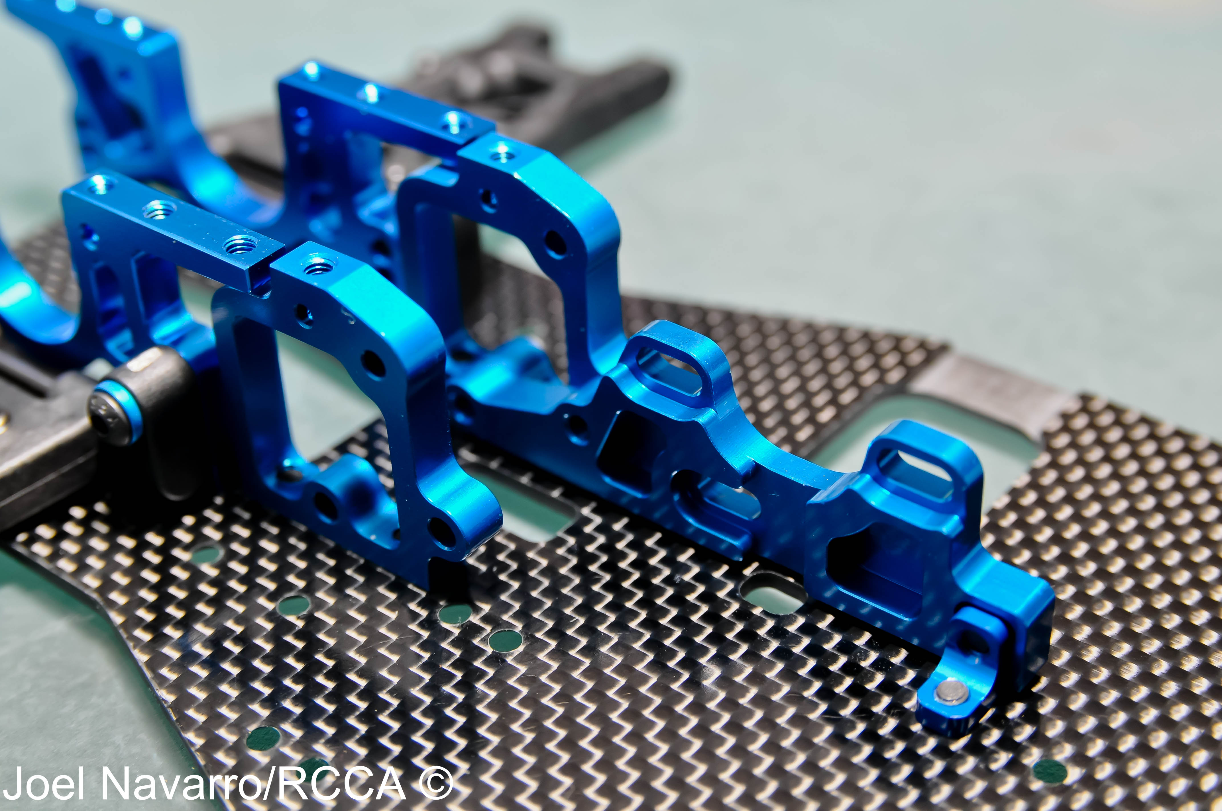
- Here’s the rear suspension assemble in its place on the chassis. The rear/front blue aluminum bulkheads are all exactly the same…more symmetrical convenience.
-
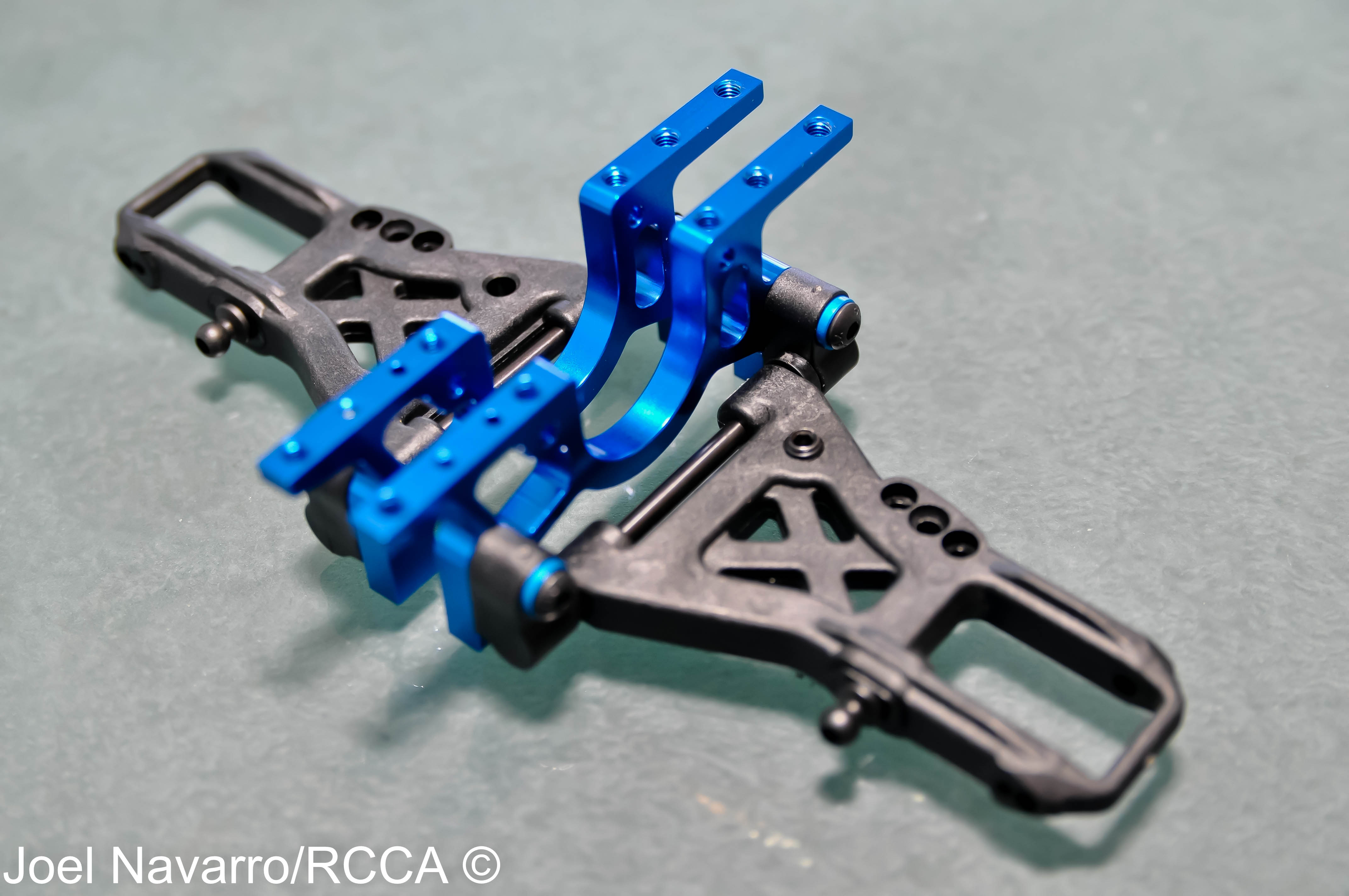
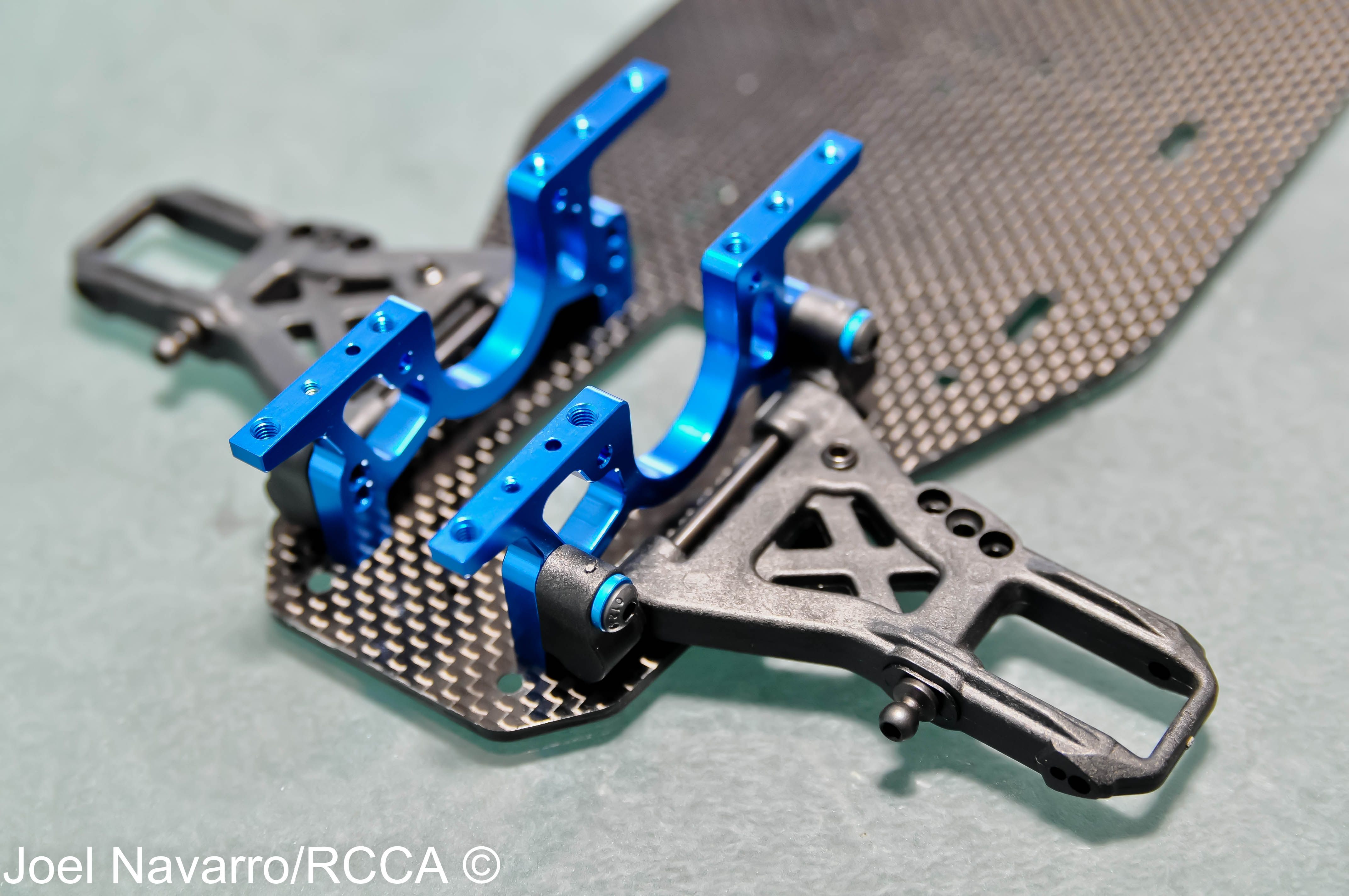
- The motor plate mounted to the mid-bulkhead via 2 button head screws, then to the chassis with an L-bracket.

-
- This 2-piece motor mount design on the TC6.1 should yield equal left/right chassis torsional flex. For convinience and easy of motor install/removal, the motor plate has 3 motor mounting holes to accommodate any size spur gear and easily access motor screws.
-
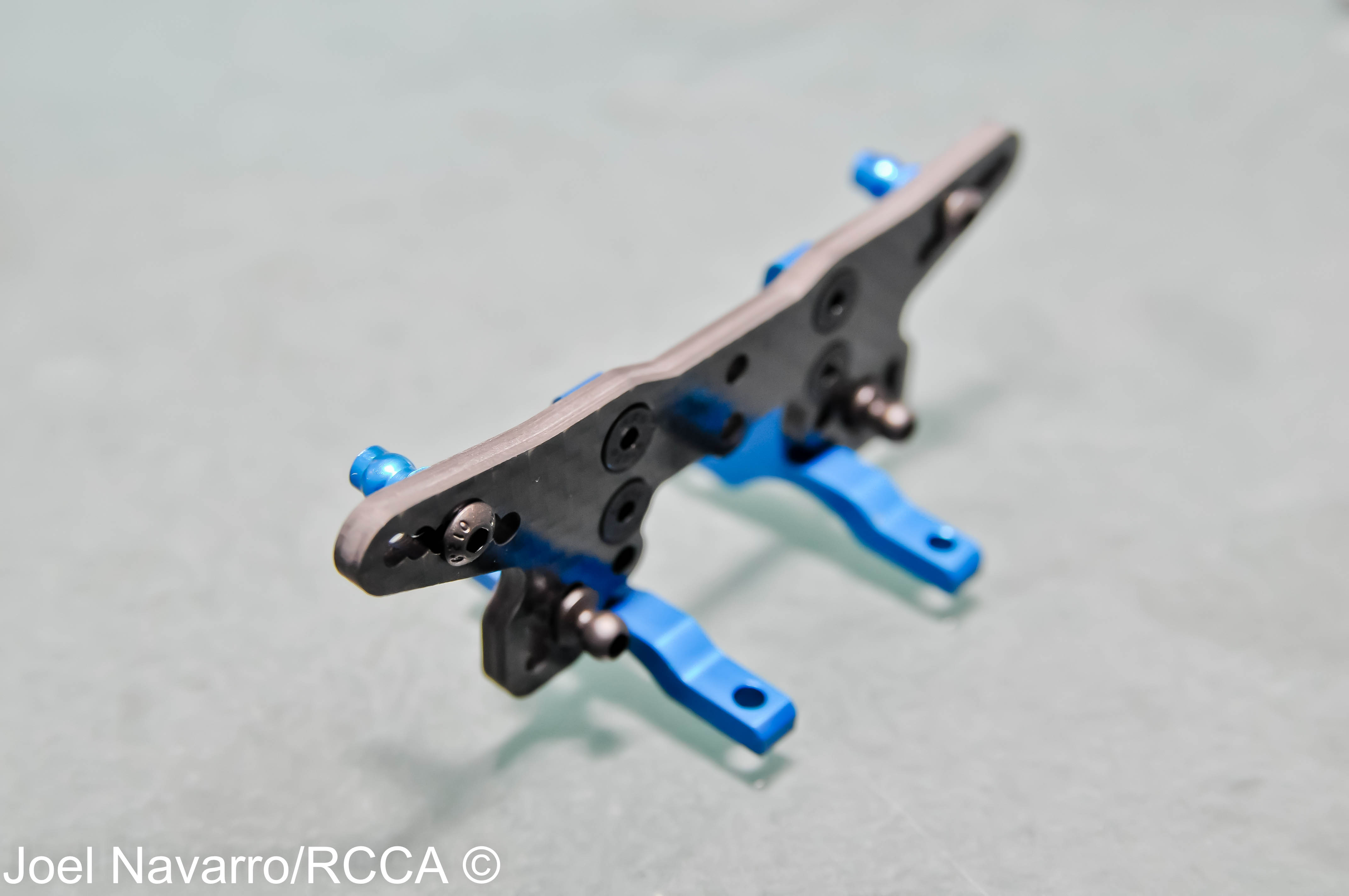
- Building the front shock tower assembly was pretty straight forward. Mounting to the upper bulkheads was achieved via 4 countersunk standard 3mm screws.
-
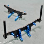
- The same steps were followed to assemble the rear shock tower assembly. Here are both finished pieces.

-
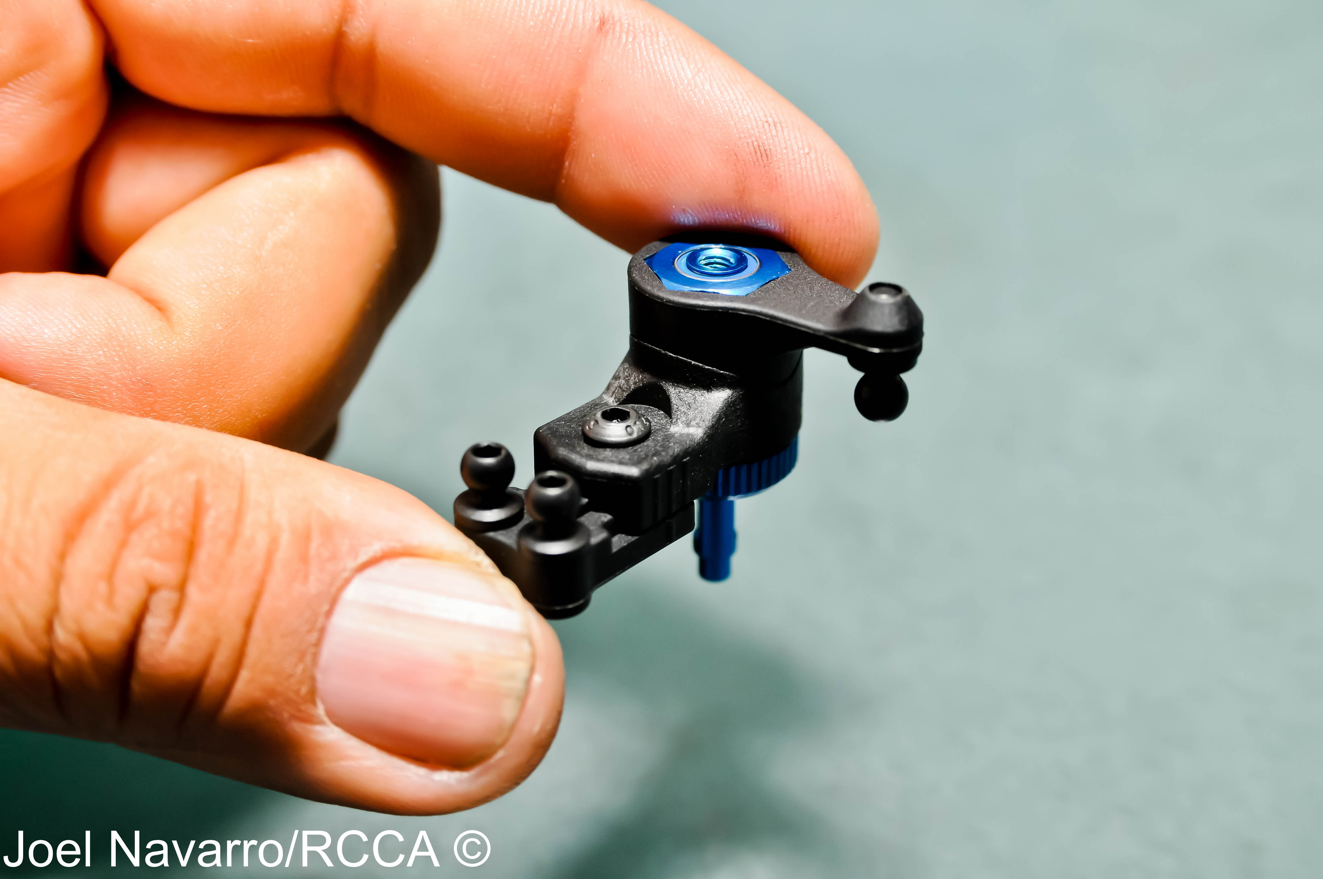
- Moving on to some of the control systems the TC6.1, the steering bellcrank was next to be assembled. Be very careful not to lose the unique c-clip that will hold the bellcrank on the blue aluminum post!

-
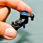
- The finished steering bellcrank can easily and quickly be adjusted without removing it from the car. You can adjust the roll center, ackerman and servo-saver tension.
-
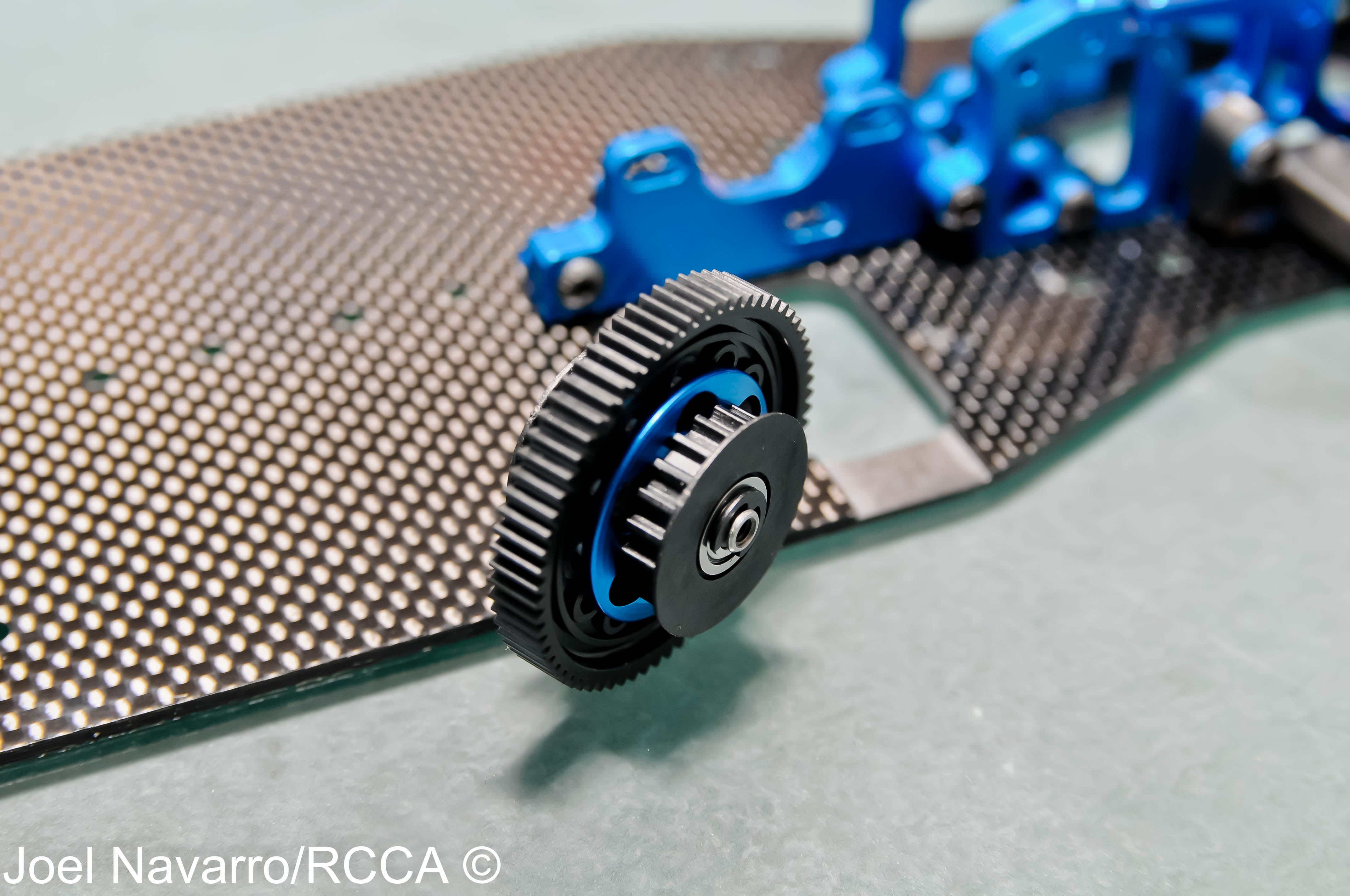
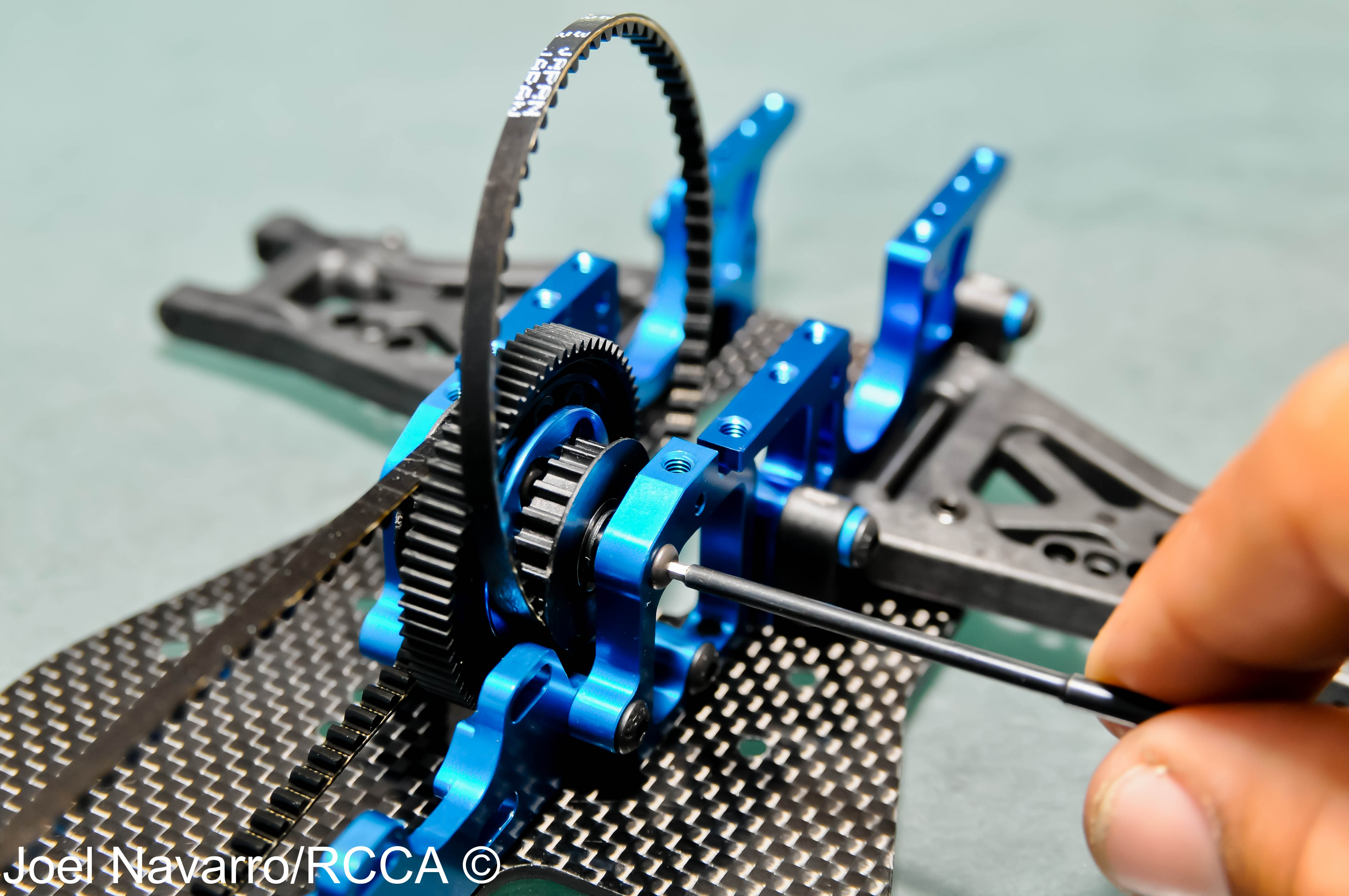
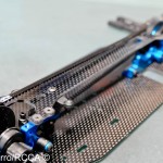
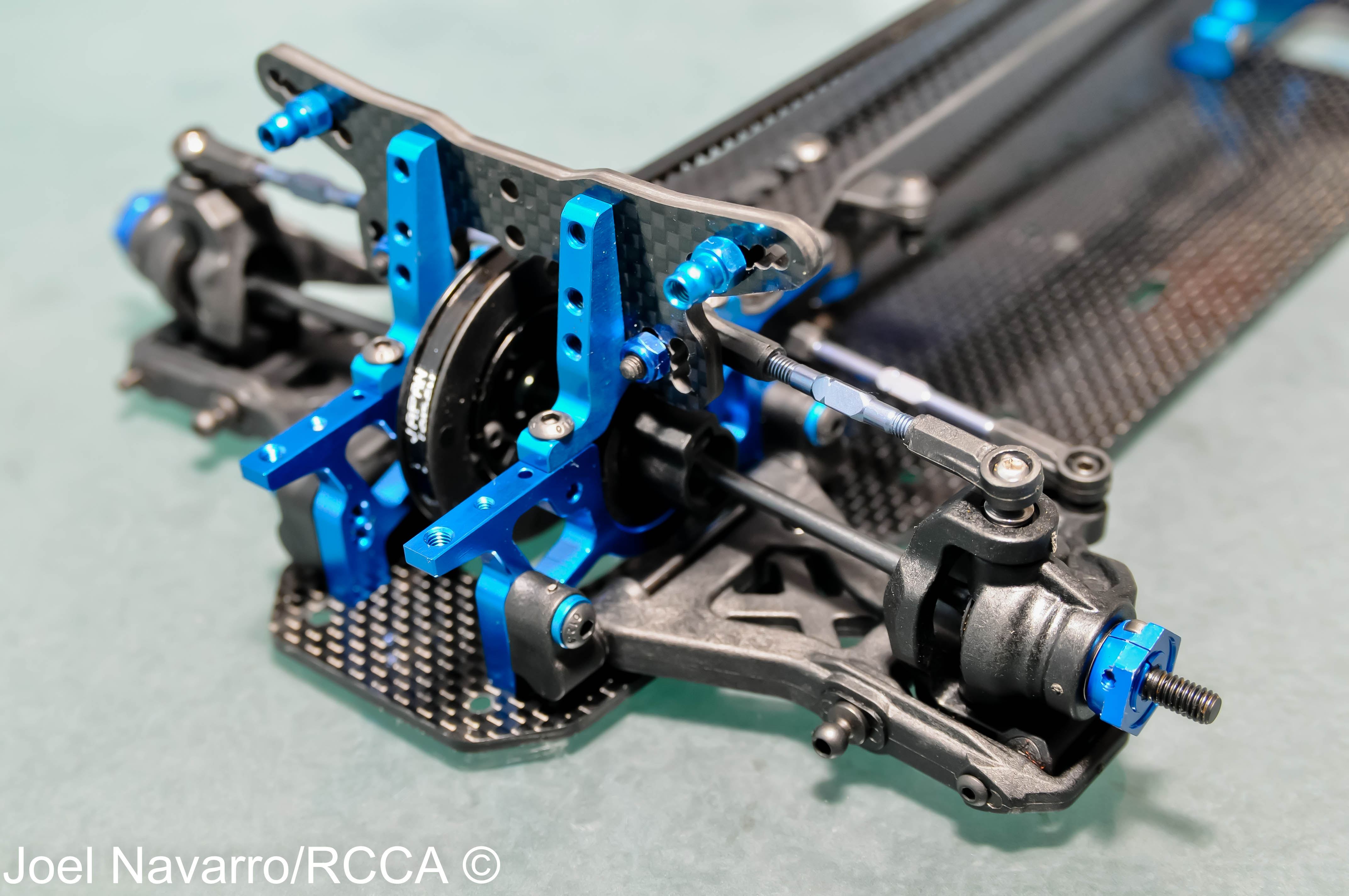
- Building the spur/shaft assembly went together very easily with minimal parts. I will be running a Reedy Sonic 17.5 brushless motor with no boost that requires this small 69 tooth spur gear (the kit comes with a 87-tooth spur) with a huge pinion gear.
-
- I’m a huge fan of how the spur gear mounts to the bulkhead via two 2.5x8mm screws. This spur mounting system will make spur gear changes super quick due to the fact you wont have to take off the upper graphite plate to get to the spur.
-
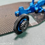
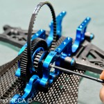
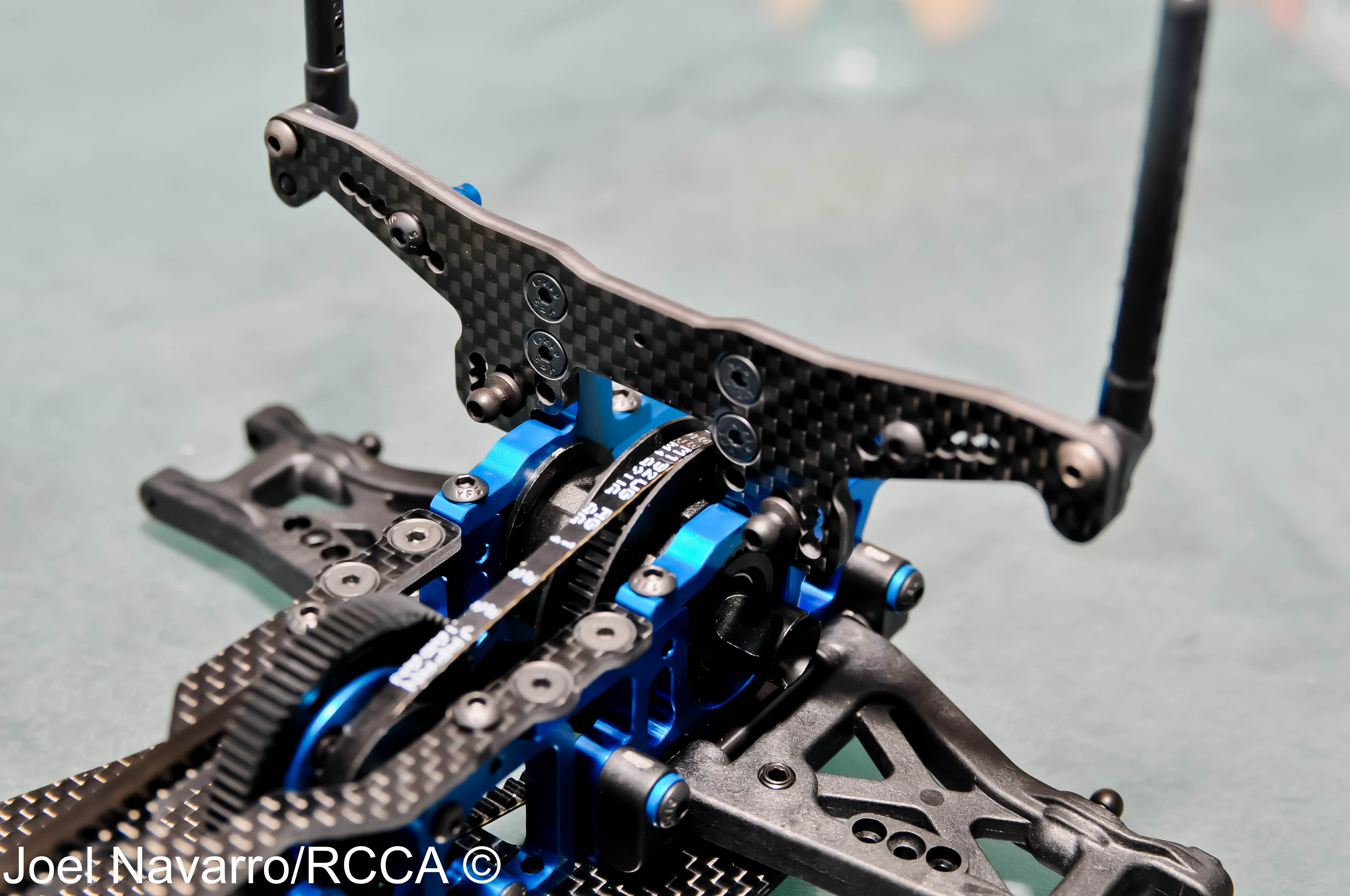
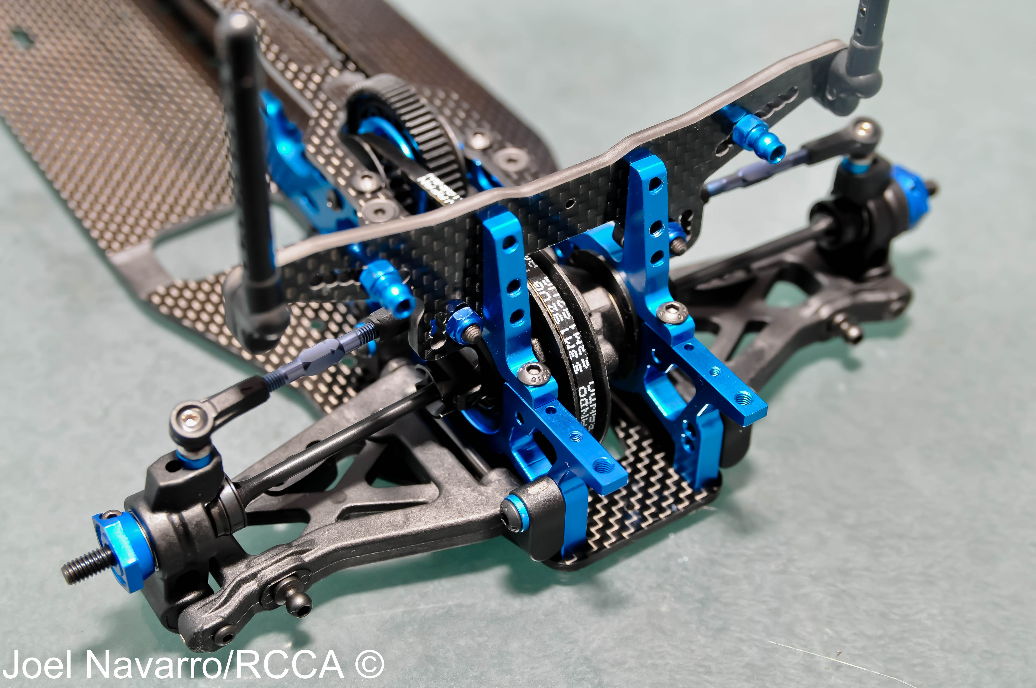
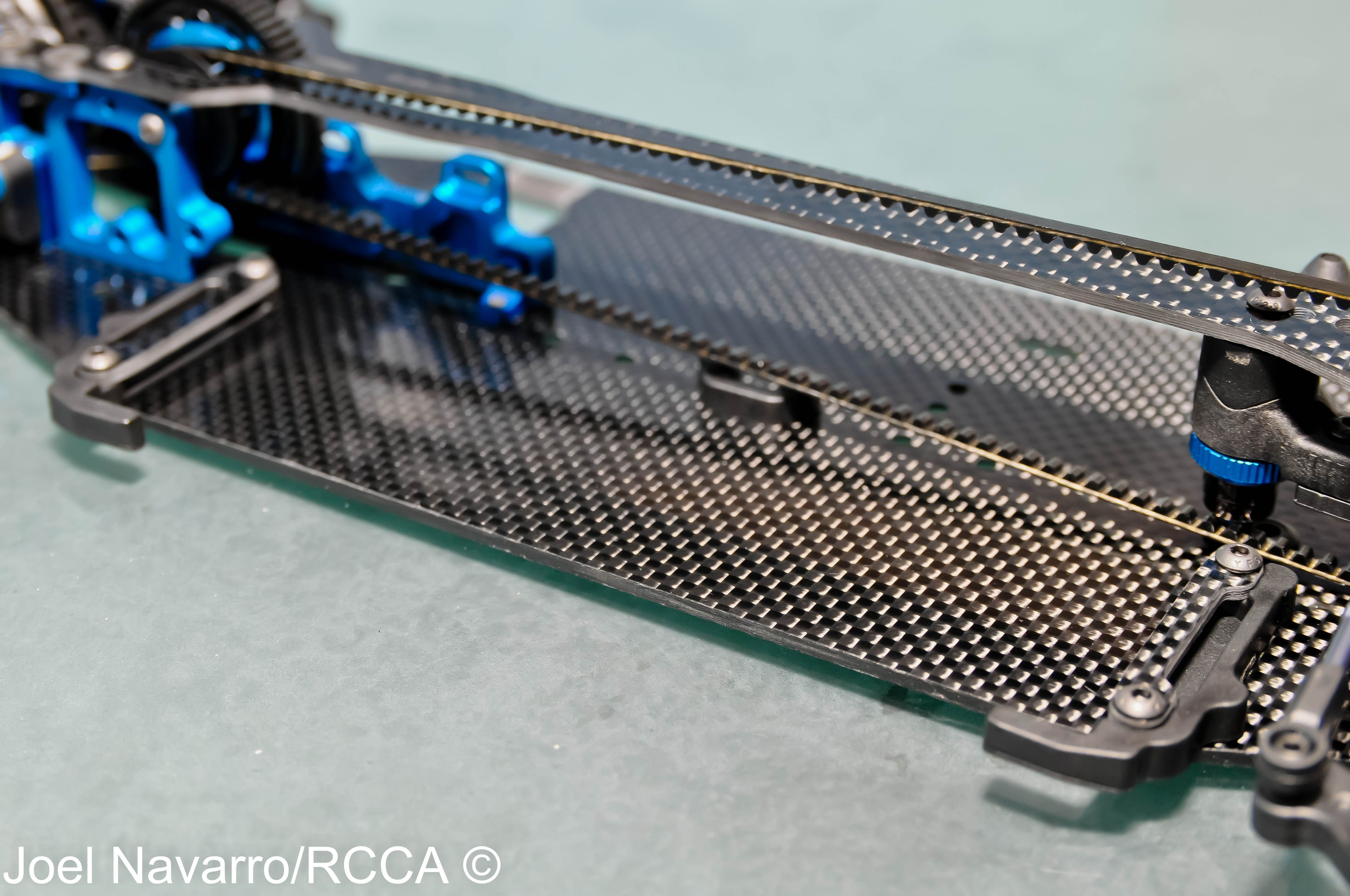
- Here is the front spool, the rear gear diff and the spur gear mounted in their places with the front/rear belts installed.
-
- The steering bellcrank mounts to the chassis via a 2-position fore/aft insert and will screw in place later to the top plate. The default ackerman mounting position is the rear hole.

-
- The graphite top plate mounted onto the TC6.1 using 11 screws. I lightly finger tightened the chassis and top plate screws in place. I will do a final tightening when the whole car is completely assembled.

-
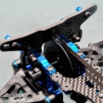
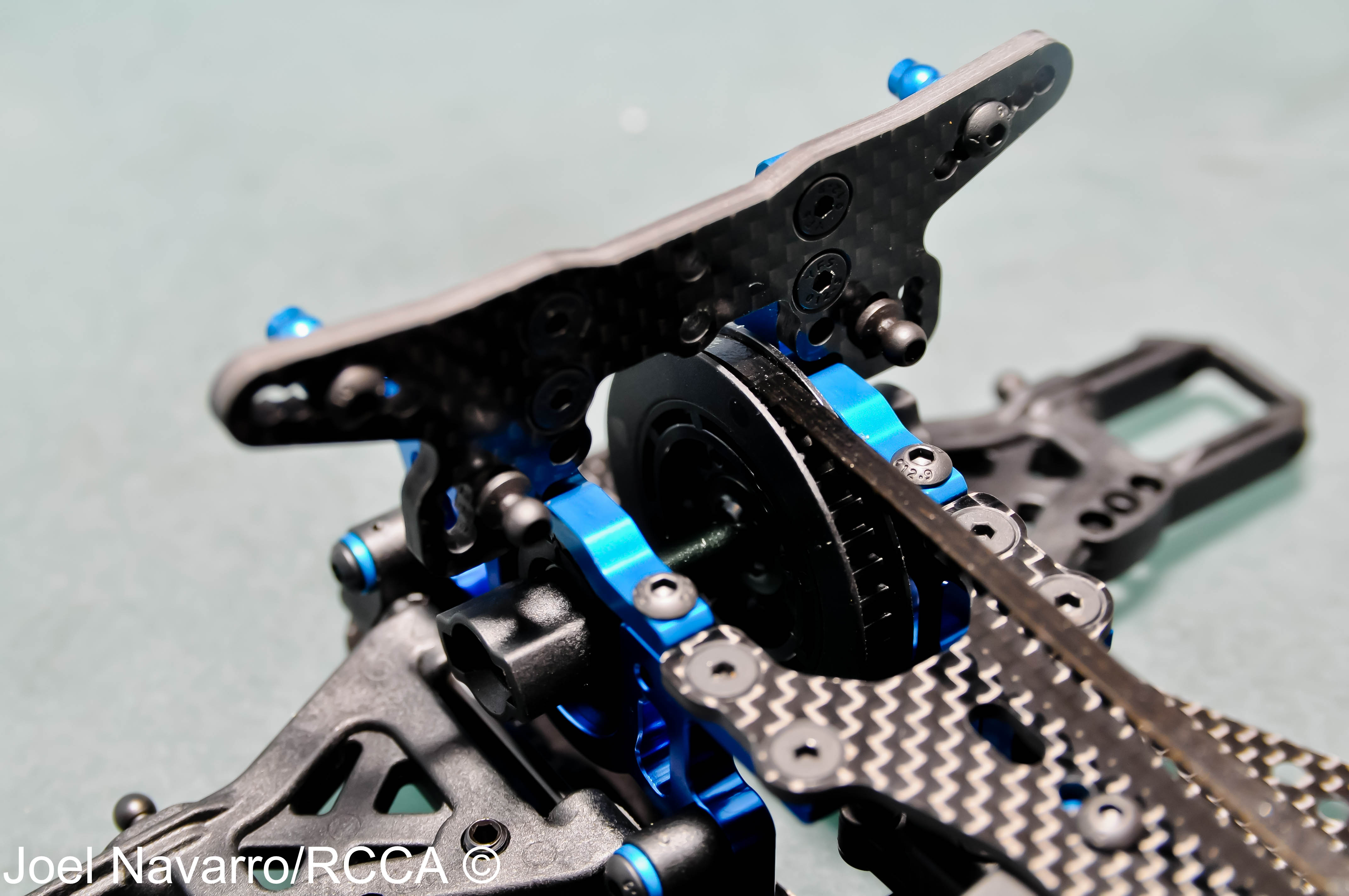
- I mounted the front shock tower/upper bulkhead assembly next with 4 button head screws. The default front belt tension was set to 8 in the bearing cam/carrier.
-
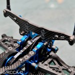
- The same steps were repeated for the rear shock tower/upper bulkhead assembly The rear default belt tension was set to the 7th position.
-
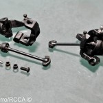
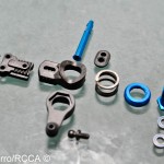
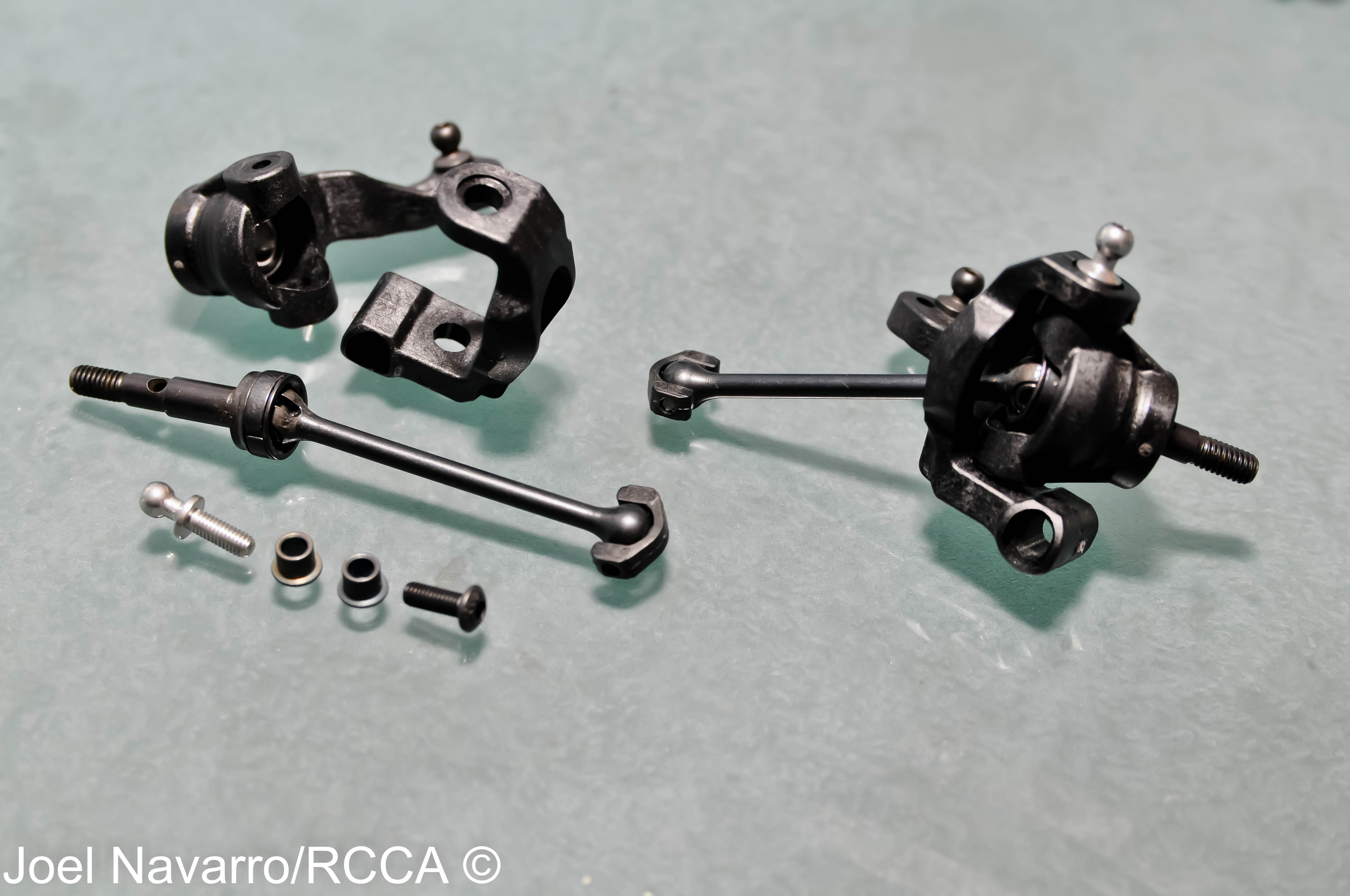
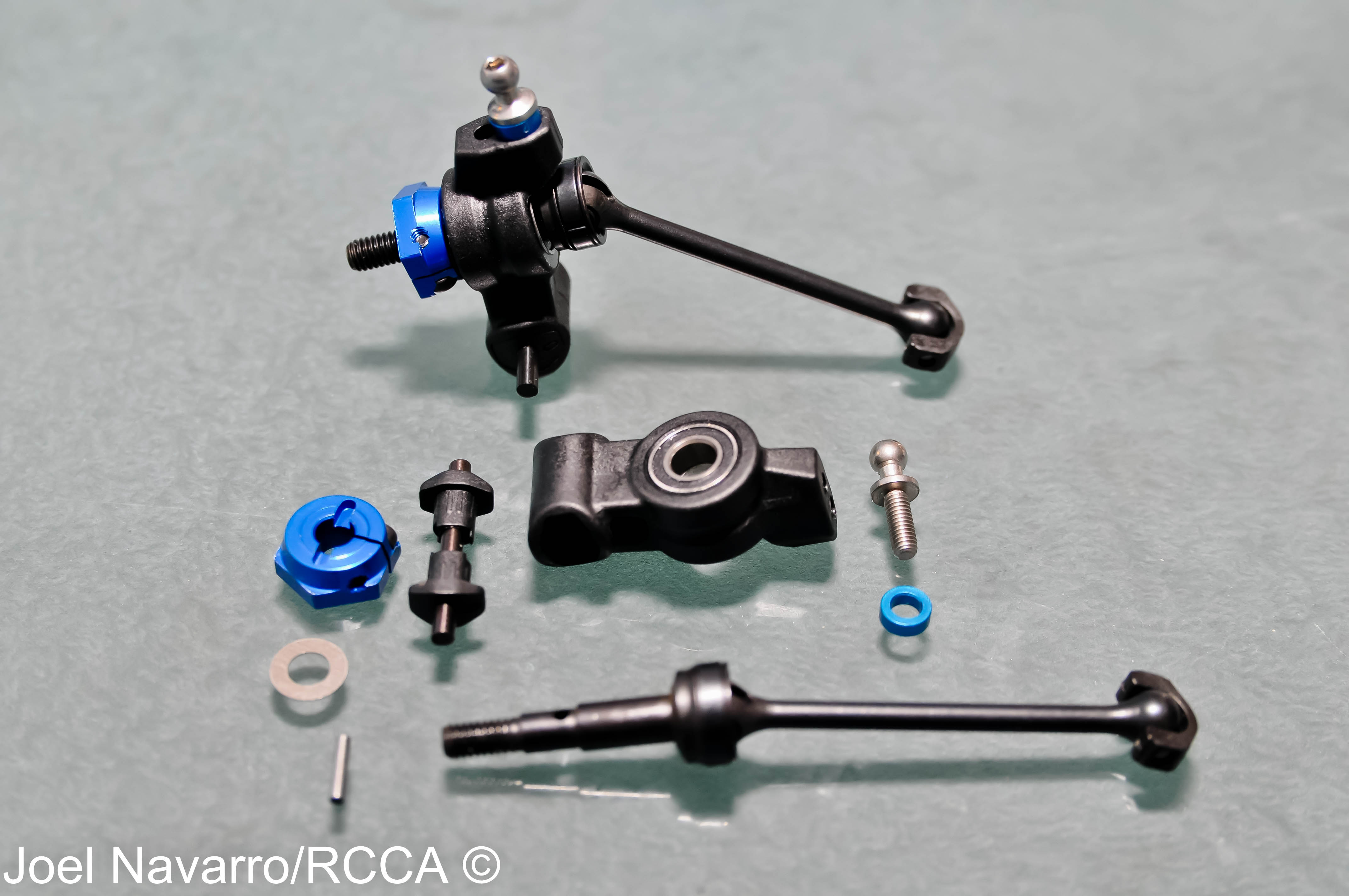
- The initial parts that will build the steering blocks are on the left and the finished preliminary unit on the right.
-
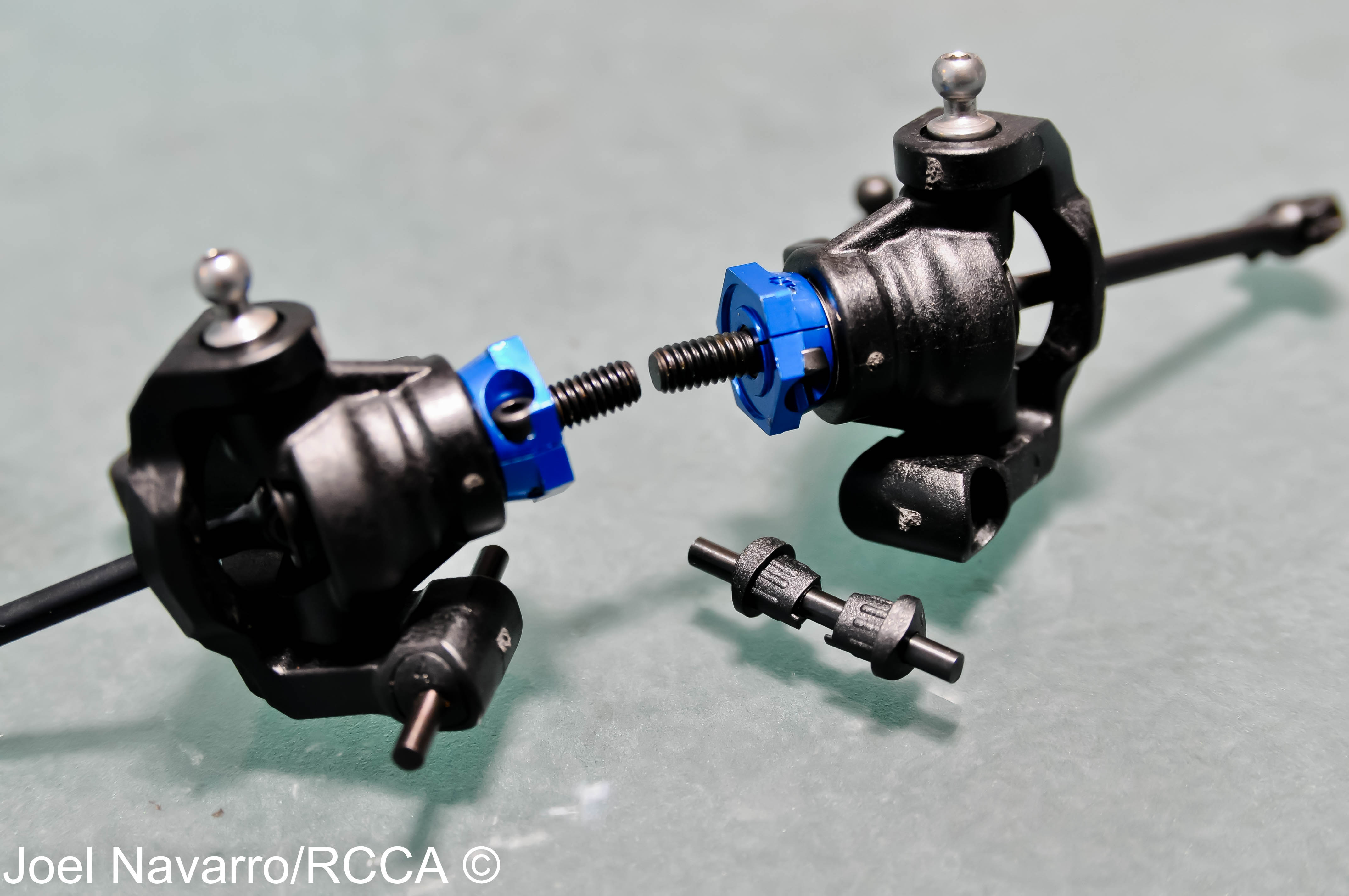
- I next mounted the blue aluminum clamping wheel hexes to the axle. The plastic “blades” on the universals will keep wear to a minimum and offer smooth power transfer to the wheels.

-
- The steering blocks are almost ready to mount. The incorporate plastic inserts that allow you to change the caster angle. A genius design that saves you money by not having to buy multiple aftermarket steering blocks to change the caster; simply change the insert.
-
- Here is the finished steering block mounted with the camber link in place. 4-degrees of caster is the initial steering block setting.
-
- The instruction book next called for snapping into place the steering linkages.
-
- Moving towards the rear of the car, it was time to build the rear hub assembly. The rear hub carrier also incorporates inserts that let you change the toe-in angle in the hub itself. The default angle is 0-degrees, but if you wish to change the toe-in angle, additional inserts are included in the TC6.1.
-
- Here are the finished rear hubs mounted on the rear suspension arms and with the camber links in place.
-
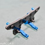
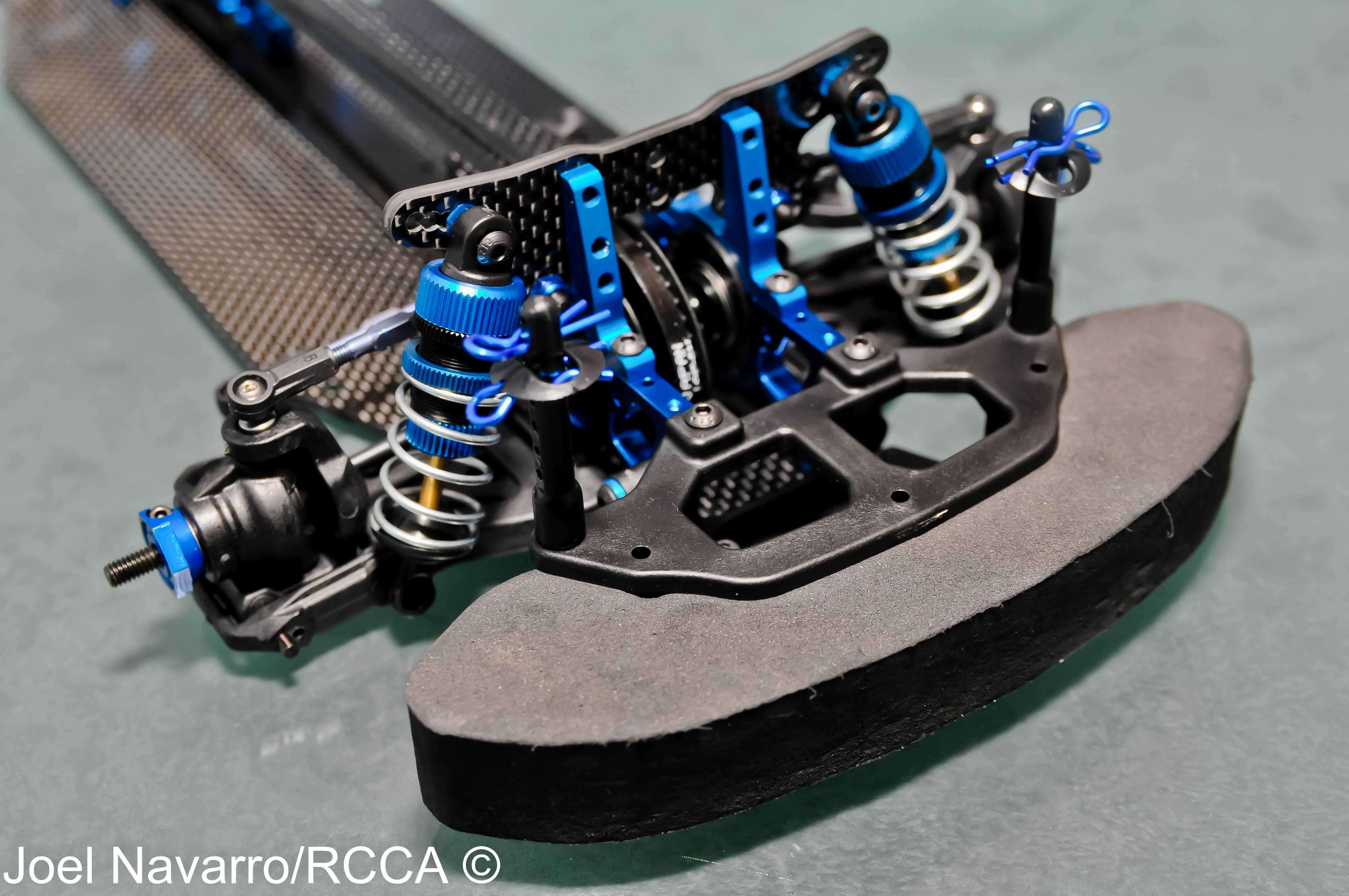
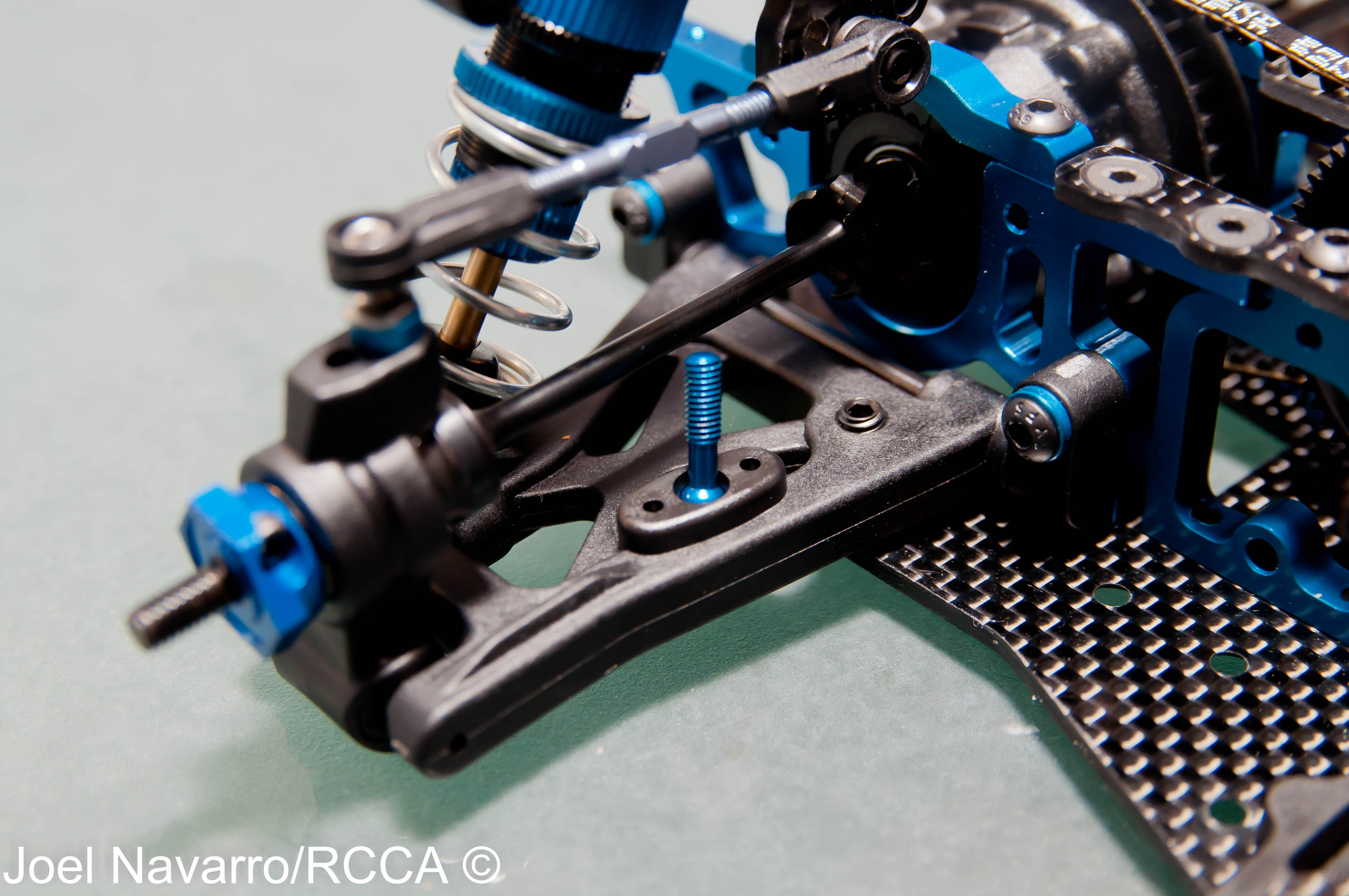
- The bumper went on next. While i was at it, I went ahead and mounted the front shocks.
-
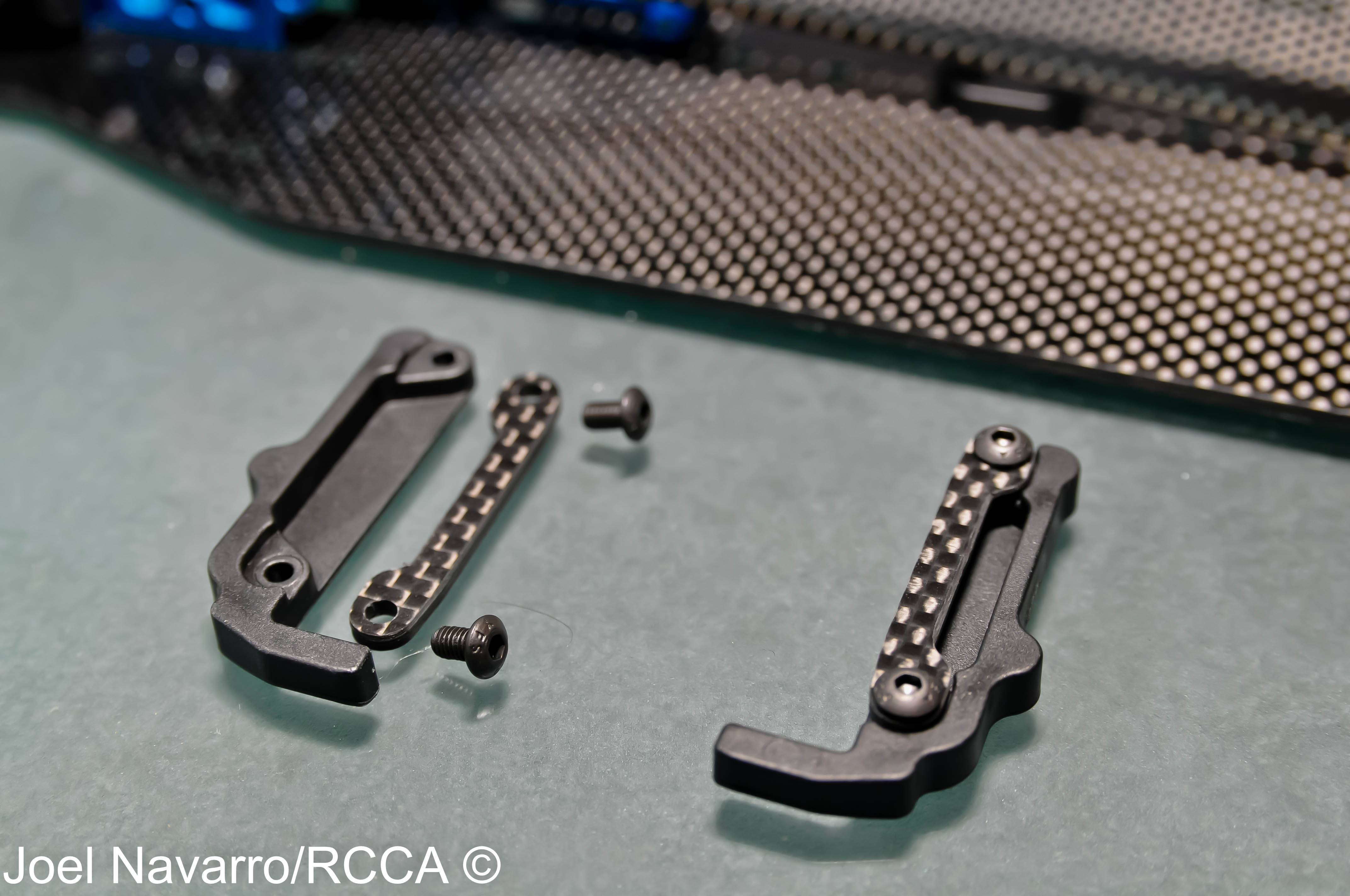
- The battery braces were next to assemble where you will use strapping tape to mount the battery. Using strapping tape versus a carbon fiber battery strap will eliminate a “dead spot” in the torsional flex of the chassis.
-
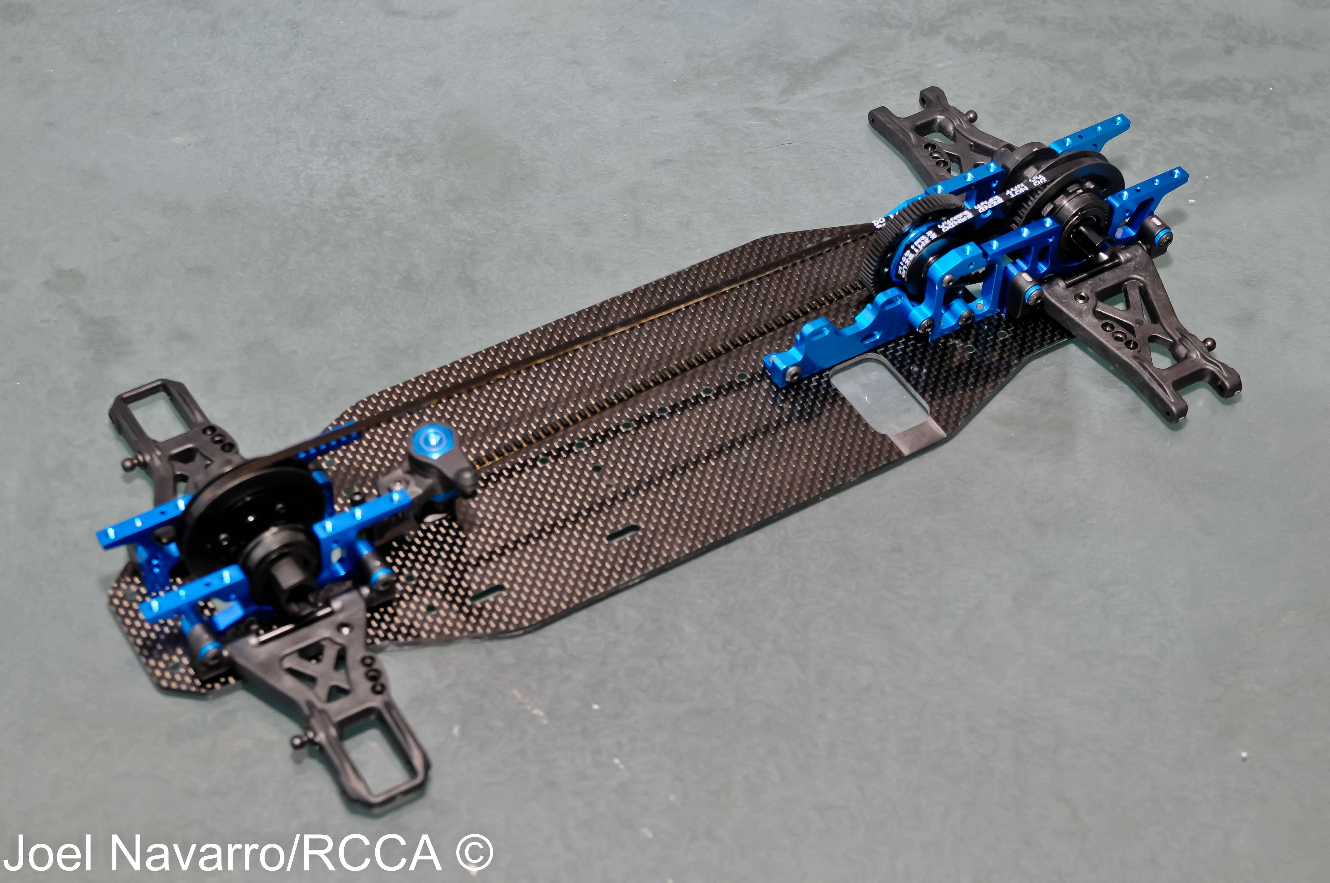
- Here are the battery braces mounted on the chassis. Having these units screwed onto the chassis versus cutting an actual slot in the chassis for strapping tape will keep the chassis closer to symmetrical on the left/right sides for consistent flex and handling.
-
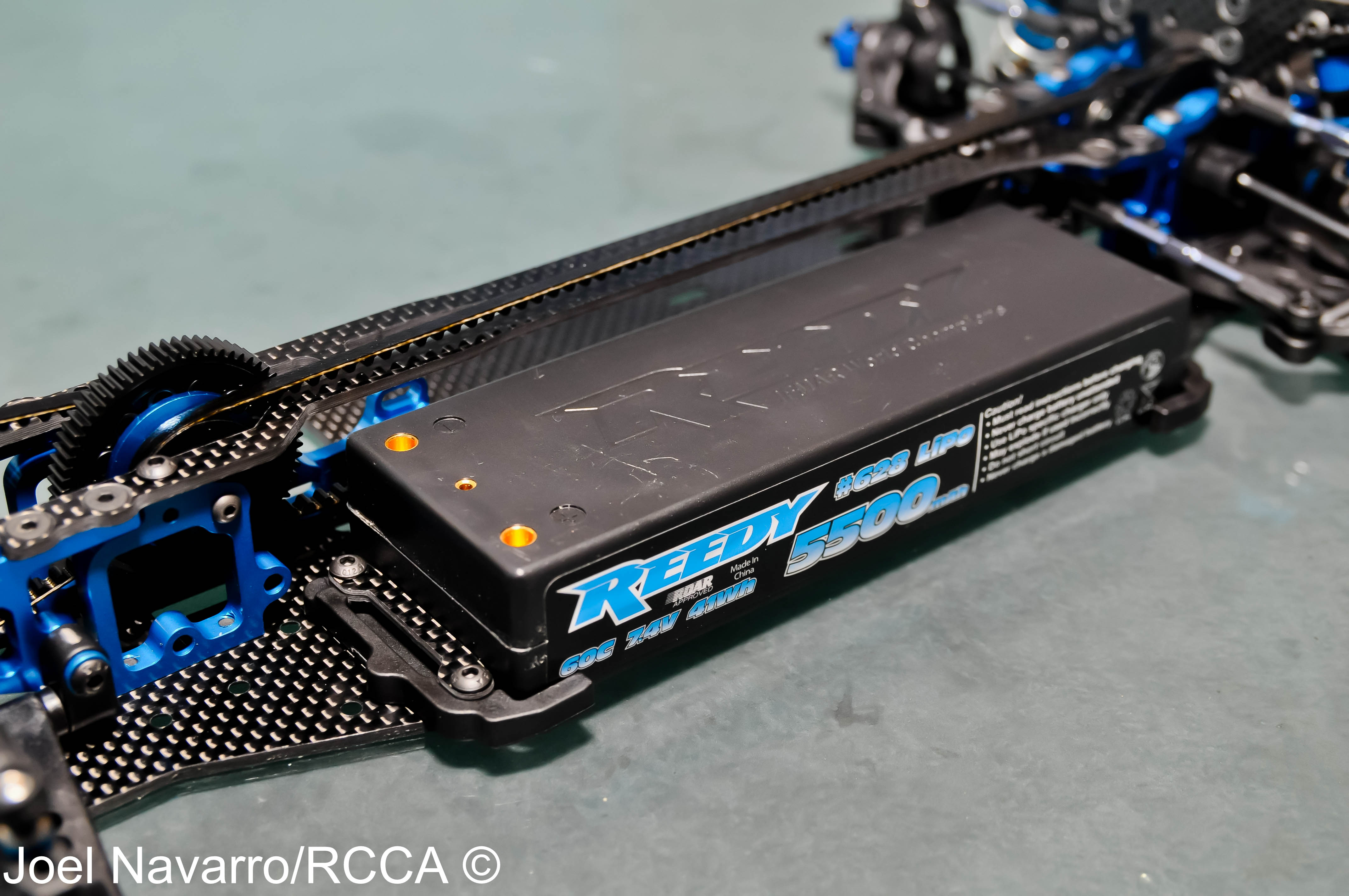
- Here’s a regular sized competition LiPo battery in place on the TC6.1. The battery braces default setting is with the battery in the forward position.
-
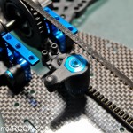
- We’re reaching the end of the build. Assembling the anti-roll bar assembly is next. First step was to mount the anti-roll bar blue aluminum stud into the arms. This smartly designed anti-roll bar mounting system allows you to quickly compensate for a tweaked/crooked/bent roll bar by turning the ball stud from underneath with your wrench to alter the height of the plastic ball cup.
-
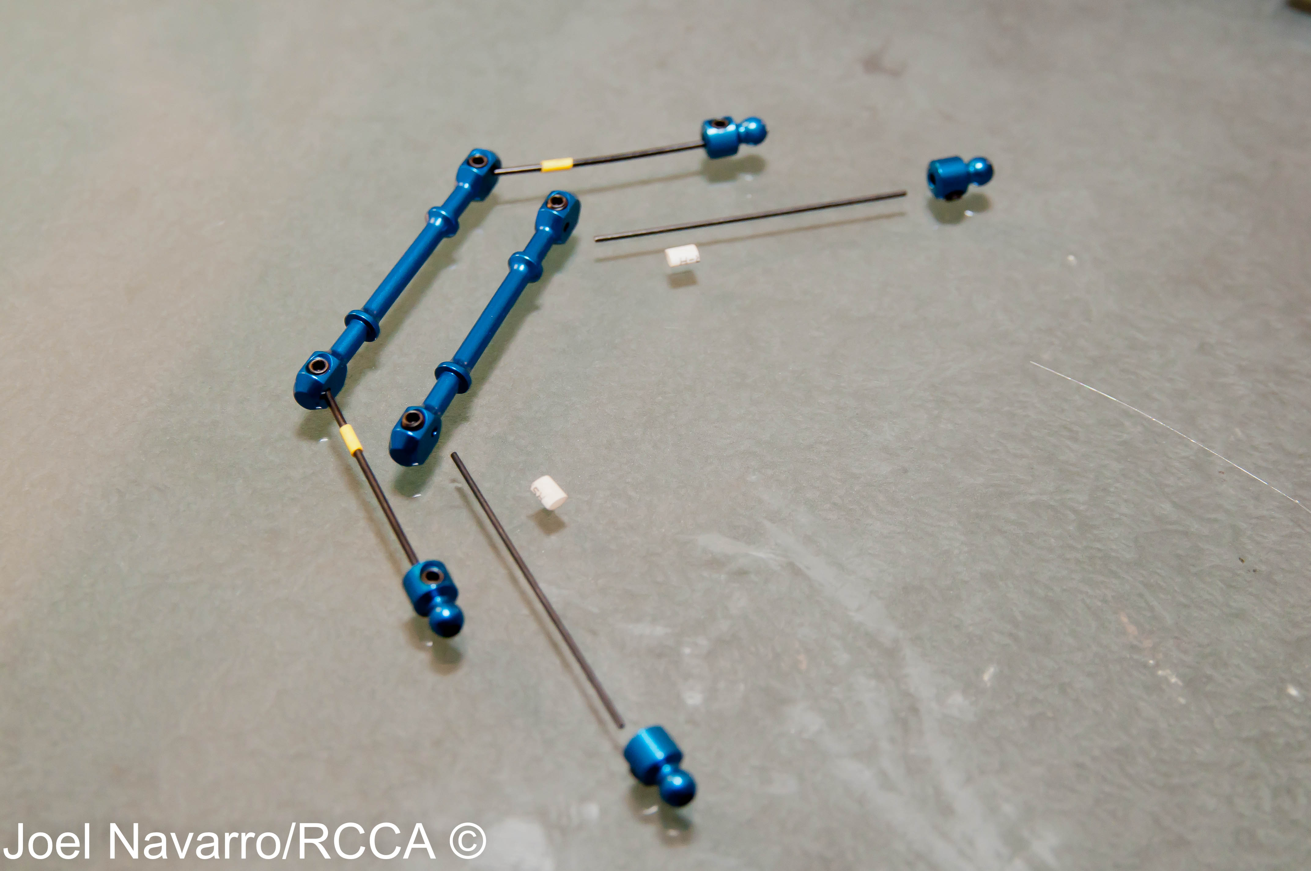
- The anti-roll bars themselves are a solid 3-piece design that assemble straight and true. Colored heat shrink helps to quickly identify the different thicknesses.
-
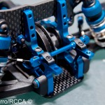
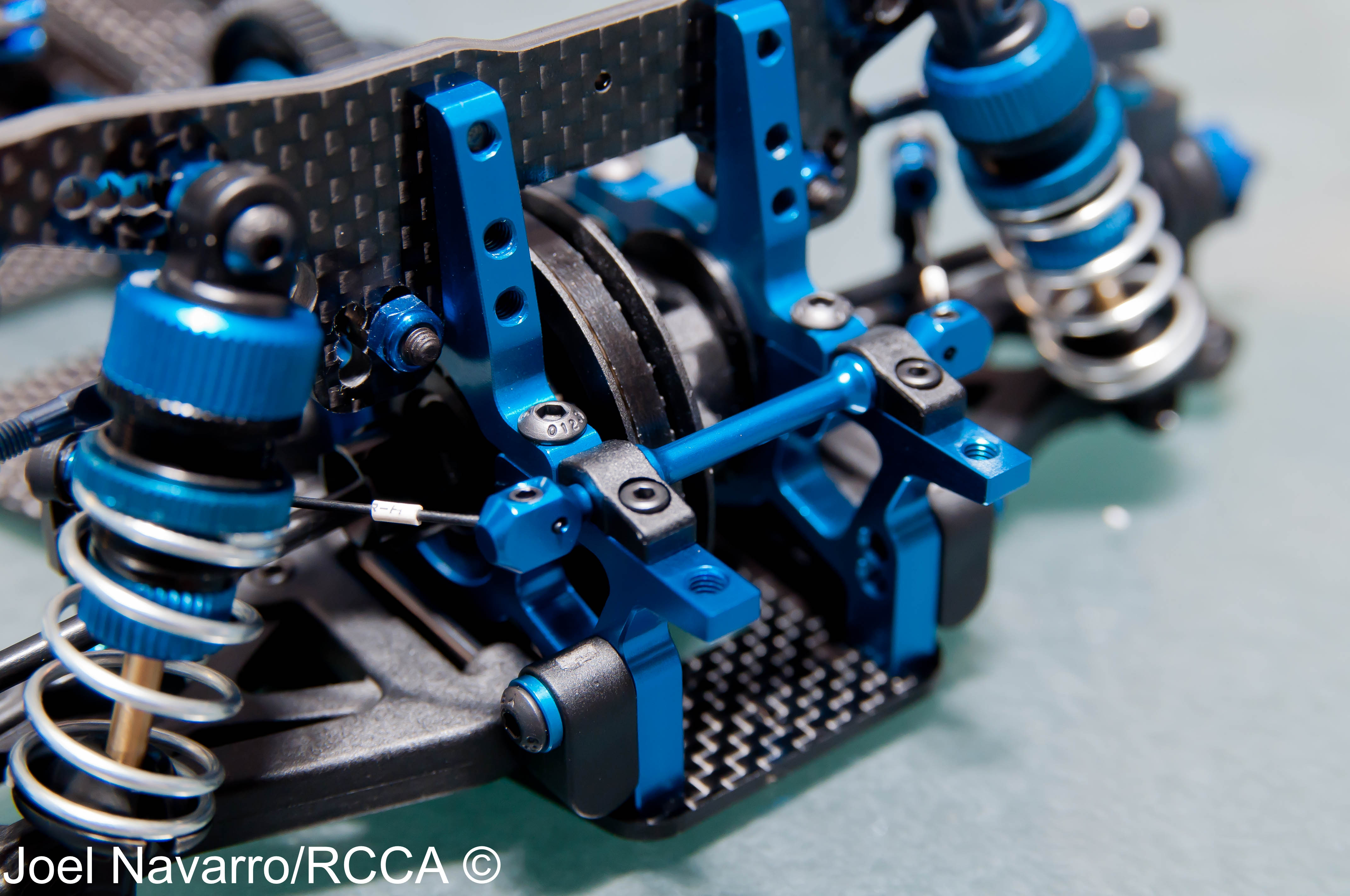
- The black plastic anti-roll bar mounts hold the bars in place. I was surprised how freely they moved with the mounting screw tightly fastened. There is very little to no slop in all the anti-roll bar assembly which should prove them a very effective influence in the TC6.1’s handling.
-
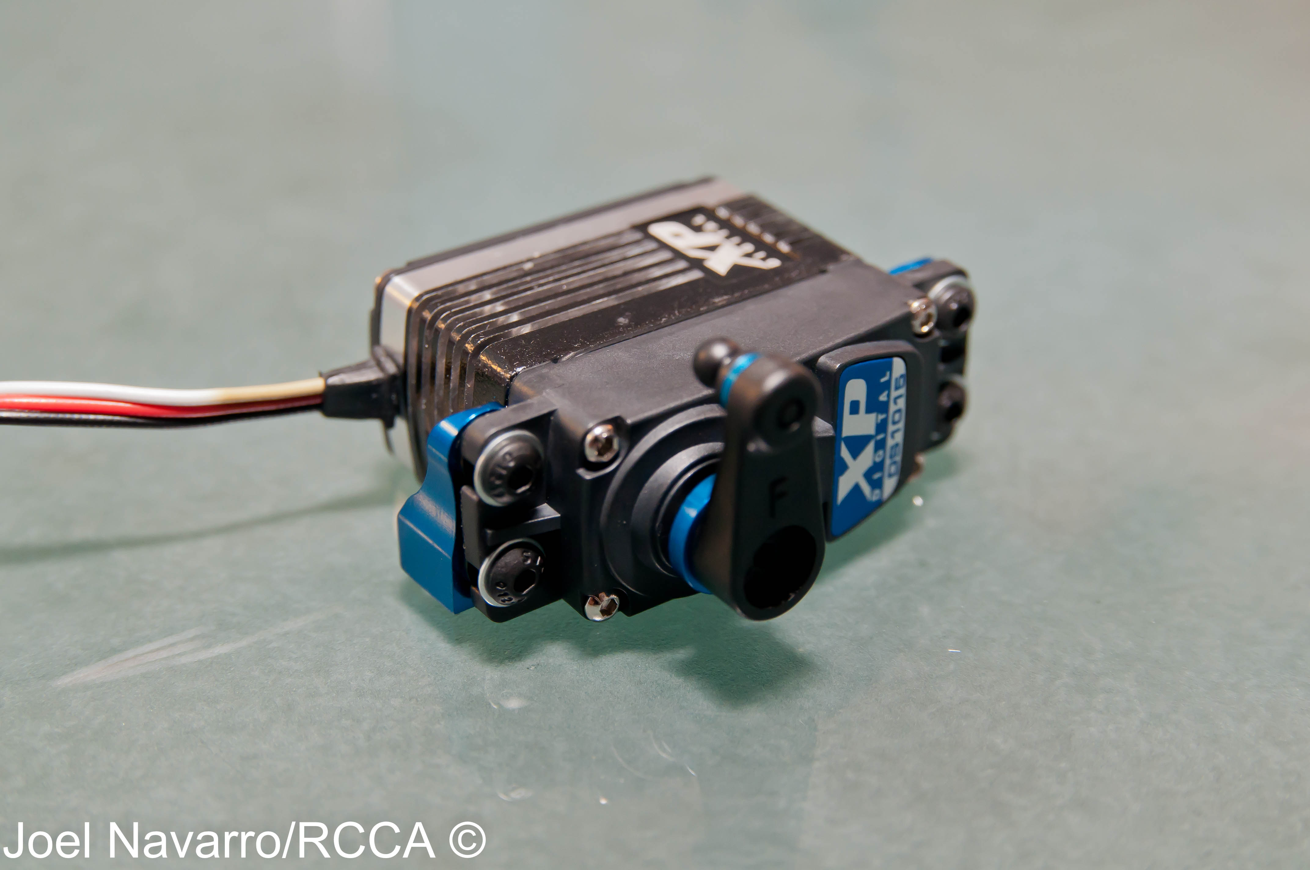
- Next on the list was to install all the servo hardware onto the XP DS1015 servo.
-
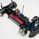
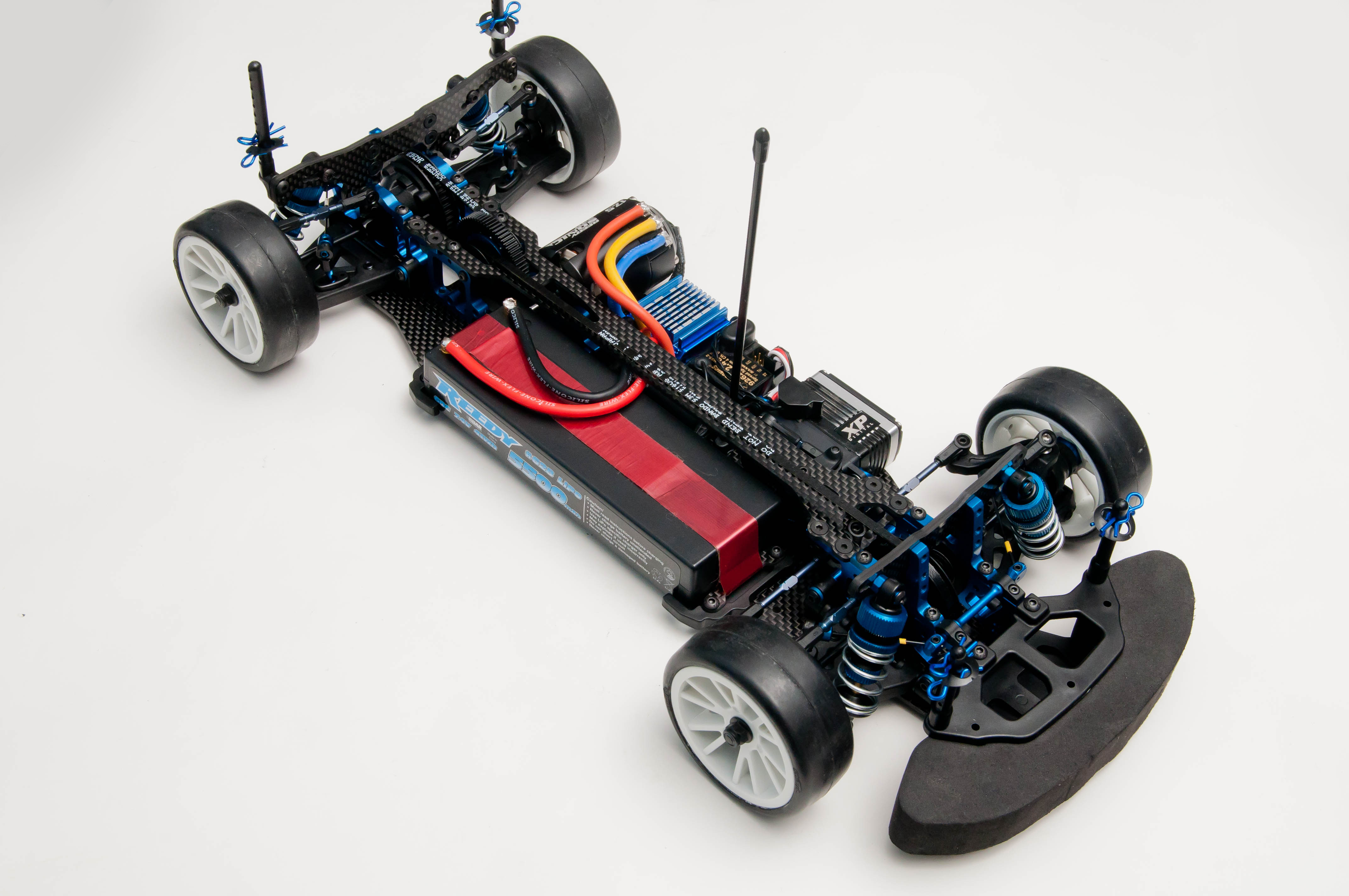
- Viola…the finished TC6.1! For tire selection, I decided to go with Solaris rubber. Solaris are standard handout tires at many major sanctioned onroad races.
-
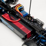
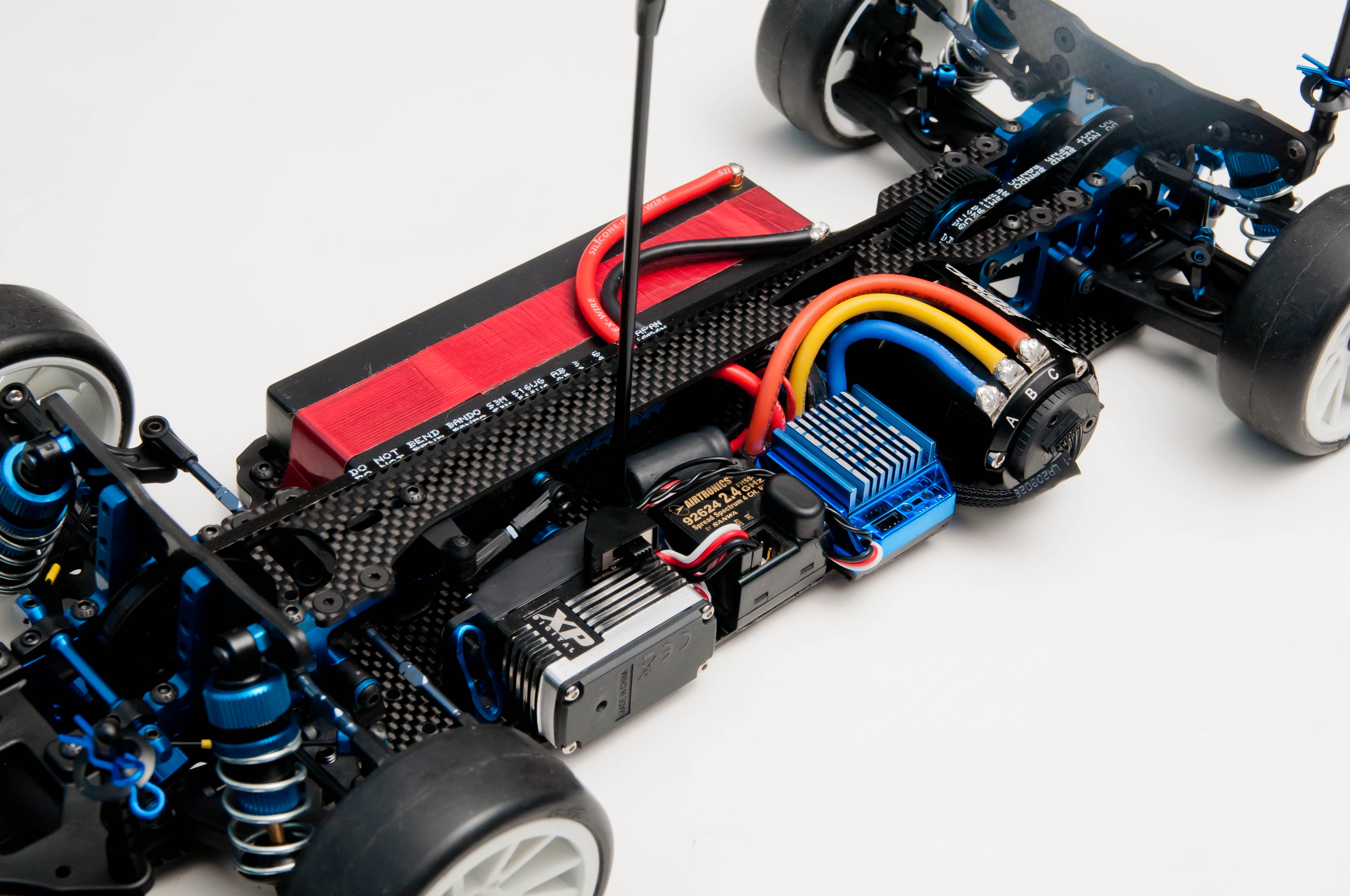
- The Reedy 7.4 Volt 5500 mAh 60C competition LiPo battery will be powering this beast.
-
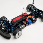
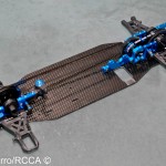
- This Associated TC6.1 sedan is ready to see some action.
-
- The electronics I will be using in this review are the XP DS1015 servo, Airtronics M11 radio, LRP Stock Spec Version 2 ESC and a Reedy Sonic 17.5 competition brushless motor.
With the TC6.1 all assembled, the only step left is to top it off with a race body and go hit the track. I plan on track testing the TC6.1 on asphalt and carpet tracks here in the SoCal area. Stay tuned and look for the full review on this killer sedan in a future issue of RC Car Action and if you’re a native to the SoCal area, I’ll see you at the track! – Joel Navarro


![RC Car Action - RC Cars & Trucks | This 1/3 scale 125cc V10 Buggy is CRAZY [VIDEO]](https://www.rccaraction.com/wp-content/uploads/2018/05/V10-HP.jpg)

 Stay up to date with the latest information, sign up for our FREE newsletter today.